
A special-shaped pipe door structure for construction machinery cab

A technology for construction machinery and special-shaped pipes, which is applied in the field of vehicle engineering, can solve problems such as easy falling off, and achieve the effects of increasing the support and bending resistance, improving the utilization rate of materials, and simplifying the materials required for fixing.

Active Publication Date: 2021-12-28
江苏奔宇车身制造有限公司
View PDF25 Cites 2 Cited by
  • Summary
  • Abstract
  • Description
  • Claims
  • Application Information

AI Technical Summary

Problems solved by technology

The above technical solution forms a mounting groove by adding a bent convex edge, so that it can be installed with accessories such as sealing strips. However, the installation of the sealing strip needs to be disassembled structurally. If the integrated sealing ring structure is adopted, it cannot be installed Inserted into the installation groove, but in fact, the elasticity of a single sealing strip decreases rapidly under multiple factors such as prolonged use time and harsh construction environment, and it is easy to fall off, which cannot meet the demand.

Method used


Image

  • A special-shaped pipe door structure for construction machinery cab
  • A special-shaped pipe door structure for construction machinery cab
  • A special-shaped pipe door structure for construction machinery cab

Examples


Embodiment 1

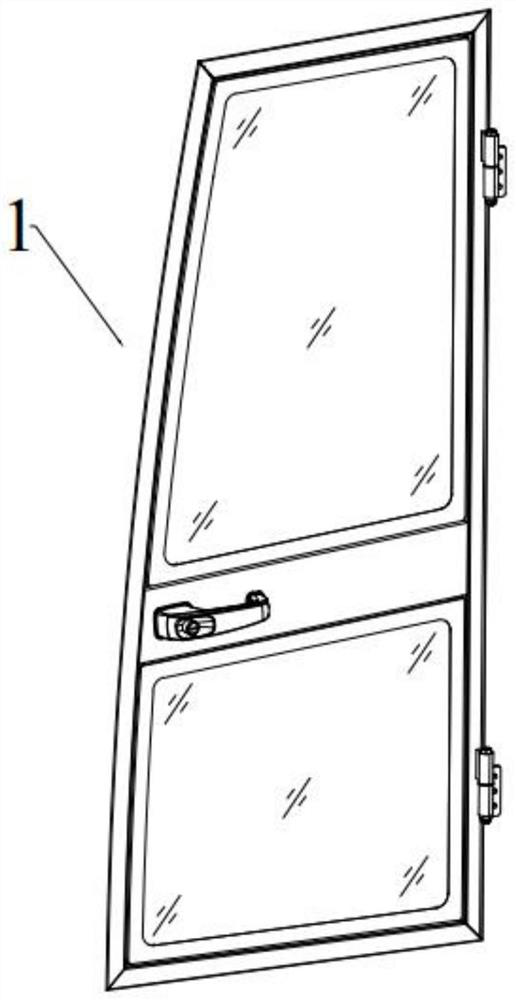
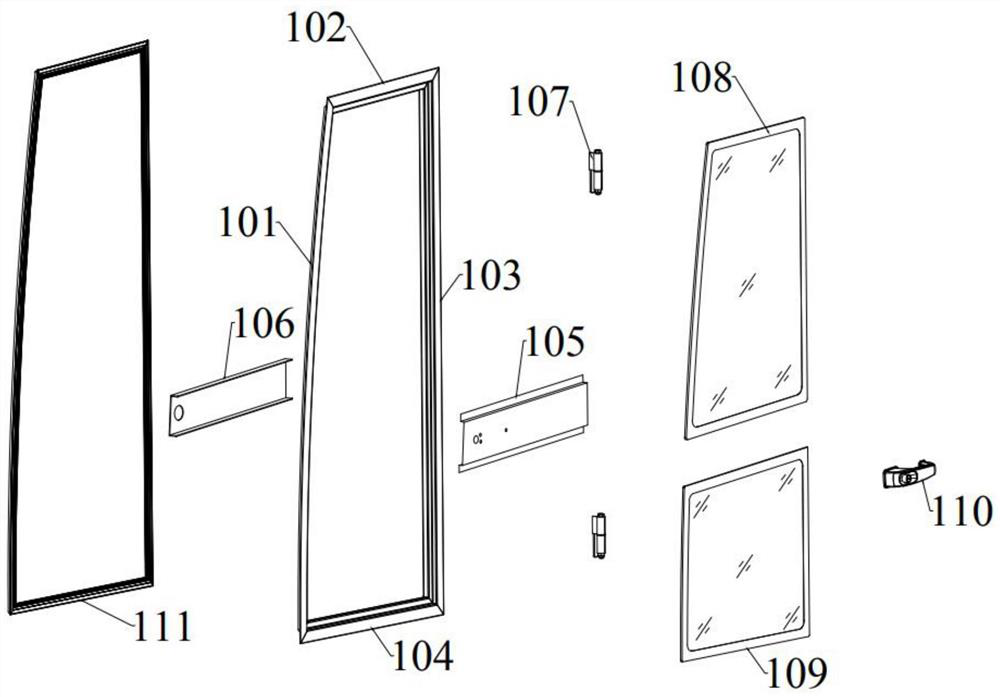
[0036] A construction machinery cab profift trunk door structure, such as figure 1 As shown, the main body structure is the door frame 1. Combine figure 2 As shown, the door frame 1 includes a pre-outer profile 101, an upper oriented tube 102, a post-mortal tube 103, a lower isofolding tube 104; wherein the front profile 101 is close to the position of the front of the front, the rear Digital tube 103 is close to The position behind the body.

[0037] The outer cross beam 105 and the inner beam 106 in the middle of the door frame 1 are applied. The lateral length of the inner and outer beam is slightly longer than the side pitch 101 and the rear transfection tube 103, and the inner and outer beam is fixed to the front axis 101 and the rear. Tube. On the 103, the two extensions are clamped.

[0038] The door handle 110 is mounted on the outer beam 105; the post-transforming tube 103 is connected to the body structure by two hinge 107 provided up and down. The door frame 1 side is p...

Embodiment 2

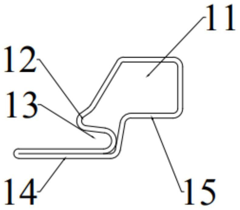
[0044] On the basis of Example 1, if Figure 4 As shown, the right angle side of the support chamber 11 in this embodiment is the arc portion 16 structure. The arc portion 16 is formed at the side of the arc, and the center of the arc portion 16 is bent at the center of the arc portion 16, which may not increase the lateral width of the shaped tube, and enhance vertical support capacity, and, in the case where the door is lateral impact Finite deformation absorbs impact energy and plays a certain protection. The specific curved rounded corners can be used in theoretical modeling analysis and experimental verification according to actual needs.

Embodiment 3

[0046] On the basis of Example 2, if Figure 5 , 7 As shown, the fold 14 of the upper and differential tube 104 of the present embodiment is laterally inclined laterally, that is, the flap 14 is connected to the glass mounting surface 15 to form a convex portion 17; convex portions 17 A angle structure is formed between the glass mounting surface 15 and the angle is an acute angle. As shown in the figure, in the actual folding 14, a cavity structure is increased to a certain extent, and the outer tube support, the bending ability, and the angle structure formed can be used to plug the upper and lower glass.

[0047] Correspond Image 6 As shown, the outer beam 105 is provided with a sub-grooved ride structure, and the convex edge is formed at an angle structure at the outer surface of the outerveral beam 105, and the upper and lower glass can be inserted into the angle structure and angle. For acute.

[0048] Specific installation, such as Figure 8 As shown, first, both ends, the lo...


PUM


Abstract

The invention discloses a special-shaped pipe door structure of an engineering machinery cab. The main structure is a door frame; the door frame is composed of a special-shaped pipe; Body structure; the upper and lower sides of the beam are respectively equipped with upper glass and lower glass; various shaped tubes are formed by multiple bending on one side; A U-shaped groove is formed between the outer surface of the support cavity and the door sealing strip is installed in the U-shaped groove; the advantage of the present invention is that the door structure is formed by splicing special-shaped pipes, which improves the utilization rate of materials, and the door frame is narrow, which improves the driver's performance. At the same time, relying on the lateral bevel design, the sealing strip can slide into the installation position without damage, which is more conducive to prolonging the service life and sealing and shock absorption effects.

Description

Technical field [0001] The present invention relates to the field of vehicle engineering technology, in particular, to a construction machinery cab profift vehicle door structure. Background technique [0002] The engineering vehicle cab car door is one of the necessary portions of the driver's access to the cab, high frequency, and needs a certain protective support, and the door should consider the necessary sealing and seismic effects. At present, the engineering machinery cab door basically uses the internal and outer panel composite structure, the manufacturing process is simple, but there is a low material utilization rate, high cost, door side frame, and the difference in the field; the common quality is also relatively heavy, bending Poor folding capacity, resulting in volatile, once the impact is received, the door deformation makes it unable to switch, which also has a common phenomenon in society, that is, driving manipulators often keeps the door open in the construct...

Claims


Application Information

Patent Timeline
Patent Type & Authority Patents(China)
IPC IPC(8): B60J5/04E02F9/16
CPCB60J5/04B60J5/042E02F9/163
Inventor 戚雪东潘健
Owner 江苏奔宇车身制造有限公司
Learn More