Stator split type movable iron core type permanent magnet linear oscillation motor

A permanent magnet linear and oscillating motor technology, applied in electromechanical devices, electrical components, electric components, etc., can solve the problems of high motor noise and vibration, short service life of permanent magnets, low output thrust density, etc., and achieve improved safety performance, Improve thrust density, reduce noise and vibration

Active Publication Date: 2021-06-18
HUAZHONG UNIV OF SCI & TECH
View PDF9 Cites 0 Cited by
  • Summary
  • Abstract
  • Description
  • Claims
  • Application Information

AI Technical Summary

Problems solved by technology

[0006] Aiming at the defects of the prior art, the object of the present invention is to provide a stator split type moving iron core permanent magnet linear oscillating motor, which aims to solve the problem of low output thrust density and long service life of permanent magnets in the existing permanent magnet linear oscillating motor. Problems with short length, high noise and vibration when the motor is running

Method used


Image

  • Stator split type movable iron core type permanent magnet linear oscillation motor
  • Stator split type movable iron core type permanent magnet linear oscillation motor
  • Stator split type movable iron core type permanent magnet linear oscillation motor

Examples


Embodiment

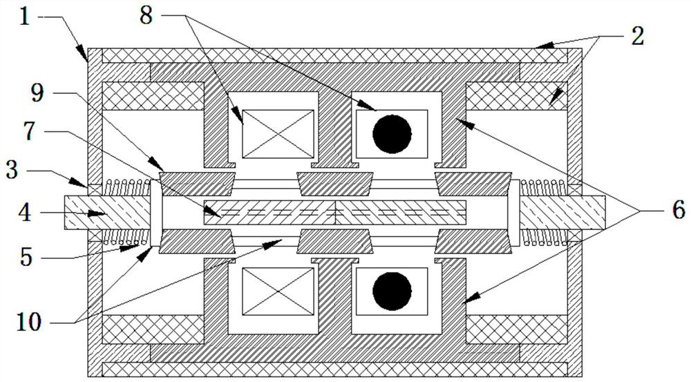
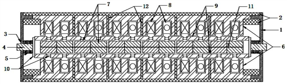
[0066] figure 1 It is a schematic diagram of the longitudinal sectional structure of the stator split type moving iron core type permanent magnet linear oscillating motor designed according to the present invention when the magnetization direction of the permanent magnet on the vertical side is the same, figure 2 It is a schematic diagram of the longitudinal section structure of the split stator moving iron core type permanent magnet linear oscillation motor designed according to the present invention when the magnetization direction of the permanent magnet on the vertical side is opposite, including a rectangular end cover 1, a casing 2, a linear motion bearing 3, Motion shaft 4, resonant spring 5, outer stator core 6, inner stator permanent magnet 7, armature winding 8, mover core 9, mover core support 10 and inner stator core 11; wherein, the outer stator core 6 is composed of two parts that are symmetrical up and down. The stator teeth of each part are equally spaced on t...


PUM


Abstract

The invention provides a stator split type movable iron core type permanent magnet linear oscillation motor, and belongs to the field of linear oscillation motors. Outer stator iron cores are symmetrically distributed at the two sides of an inner stator permanent magnet; rotor iron cores are symmetrically distributed between the outer stator iron core and the inner stator permanent magnet at equal intervals; a resonance spring is sleeved on the motion shaft; a motion shaft is connected to the geometric center of the side end of the rotor iron core bracket; the armature winding comprises two groups of coils and is connected with a sine alternating current source during use; the inner stator permanent magnet comprises a plurality of sub permanent magnets with the same size, the magnetizing directions are all vertical directions, and the magnetizing directions of the adjacent sub permanent magnets on the horizontal side are different; when the magnetizing directions of the adjacent sub permanent magnets in the vertical side are opposite, the inner stator iron core is additionally arranged between the two sub permanent magnets, two groups of coils are reversely connected in series or in parallel, and otherwise, the two groups of coils are connected in series or in parallel in the same direction; according to the invention, the service life of the permanent magnet is prolonged, the output thrust density is improved, and the noise and vibration of motor operation are reduced.

Description

technical field [0001] The invention belongs to the field of linear oscillating motors, and more specifically relates to a stator split type moving iron core permanent magnet linear oscillating motor. Background technique [0002] The traditional implementation of bidirectional linear reciprocating motion such as air compressors is: a rotary motor converts circular motion into linear motion through a crank connecting rod, thereby driving the piston to move. There are two main ways to improve the efficiency of this compressor: one is to improve the efficiency of the motor, and the other is to improve the efficiency of the transmission. However, due to the existence of multiple intermediate links, the overall efficiency of the compressor is still low. At the same time, there are many other defects in the traditional rotary compressor structure, mainly reflected in the complex structure, large volume, high noise and low efficiency. Since the permanent magnet linear oscillatio...

Claims


Application Information

Patent Timeline
Patent Type & Authority Applications(China)
IPC IPC(8): H02K41/02H02K41/03H02K16/04H02K33/00
CPCH02K41/02H02K41/031H02K16/04H02K33/00
Inventor 徐伟张娅平张祎舒李想柏丽丽
Owner HUAZHONG UNIV OF SCI & TECH
Why Eureka
Try Eureka