
System for separating concrete with different strength grades in beam-column joint core area and application

A beam-column joint and strength level technology, applied in the construction, building structure, processing of building materials, etc., can solve the problems of labor-intensive, complicated installation, difficult, etc., and achieve labor cost saving, convenient dismantling, and simple operation. Effect

Pending Publication Date: 2021-06-18
福建建工工程集团有限公司 +1
View PDF0 Cites 1 Cited by
  • Summary
  • Abstract
  • Description
  • Claims
  • Application Information

AI Technical Summary

Problems solved by technology

The traditional technology of separating concrete with different strength grades in the core area of ​​beam-column joints is labor-intensive and complicated to install, and because there are many beams anchored, it is easy to cause the steel mesh structure to be unstable and broken when passing through the steel mesh, causing high-grade concrete to flow to low-grade concrete. If the steel wire mesh cannot be taken out, the on-site construction is difficult. If the installation is not accurate, the steel mesh will be exposed after the pouring is completed, and additional manual cleaning will be required in the later stage, resulting in a waste of human resources.
Therefore, the traditional concrete separation technology of different strength grades in the core area of ​​beam-column joints can no longer meet the needs of on-site construction.

Method used


Image

  • System for separating concrete with different strength grades in beam-column joint core area and application
  • System for separating concrete with different strength grades in beam-column joint core area and application
  • System for separating concrete with different strength grades in beam-column joint core area and application

Examples


Embodiment Construction

[0027] The technical solution of the present invention will be clearly and completely described below in conjunction with the accompanying drawings and specific embodiments. In the description of the present invention, it should be noted that the terms "center", "upper", "lower", "left", "right", "vertical", "horizontal", "inner", "outer" etc. The indicated orientation or positional relationship is based on the orientation or positional relationship shown in the drawings, and is only for the convenience of describing the present invention and simplifying the description, rather than indicating or implying that the referred device or element must have a specific orientation, or in a specific orientation. construction and operation, therefore, should not be construed as limiting the invention. In addition, the terms "first", "second", and "third" are used for descriptive purposes only, and should not be construed as indicating or implying relative importance.

[0028] In the de...


PUM


Abstract

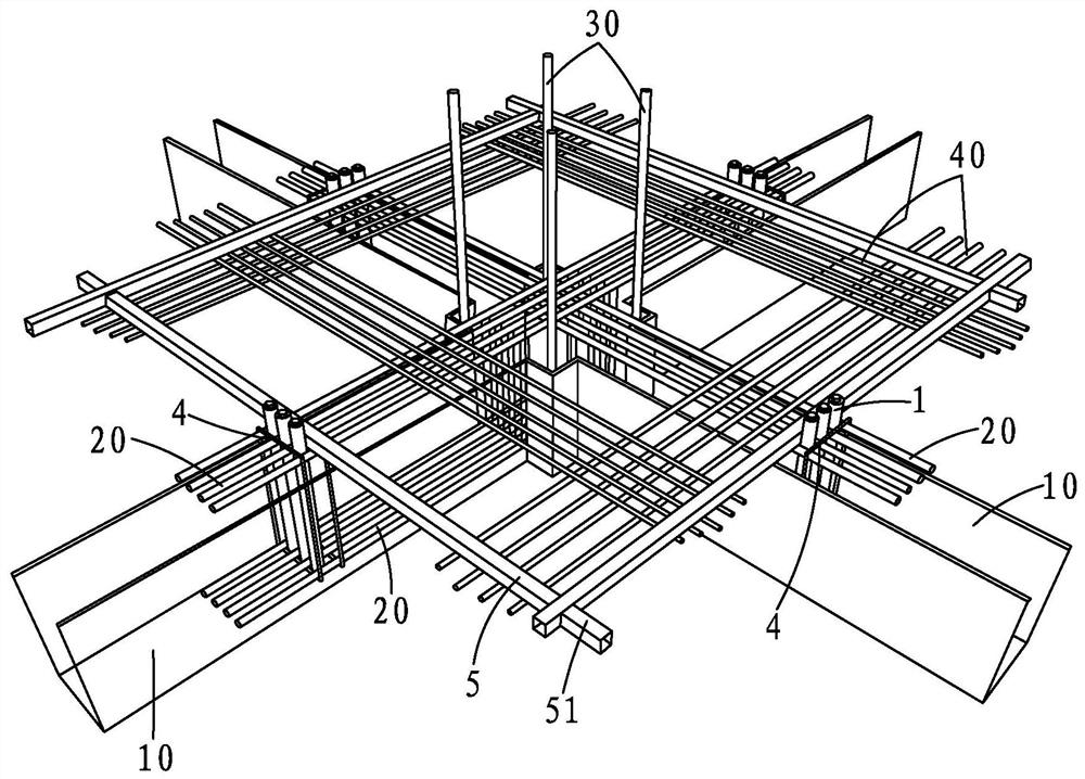
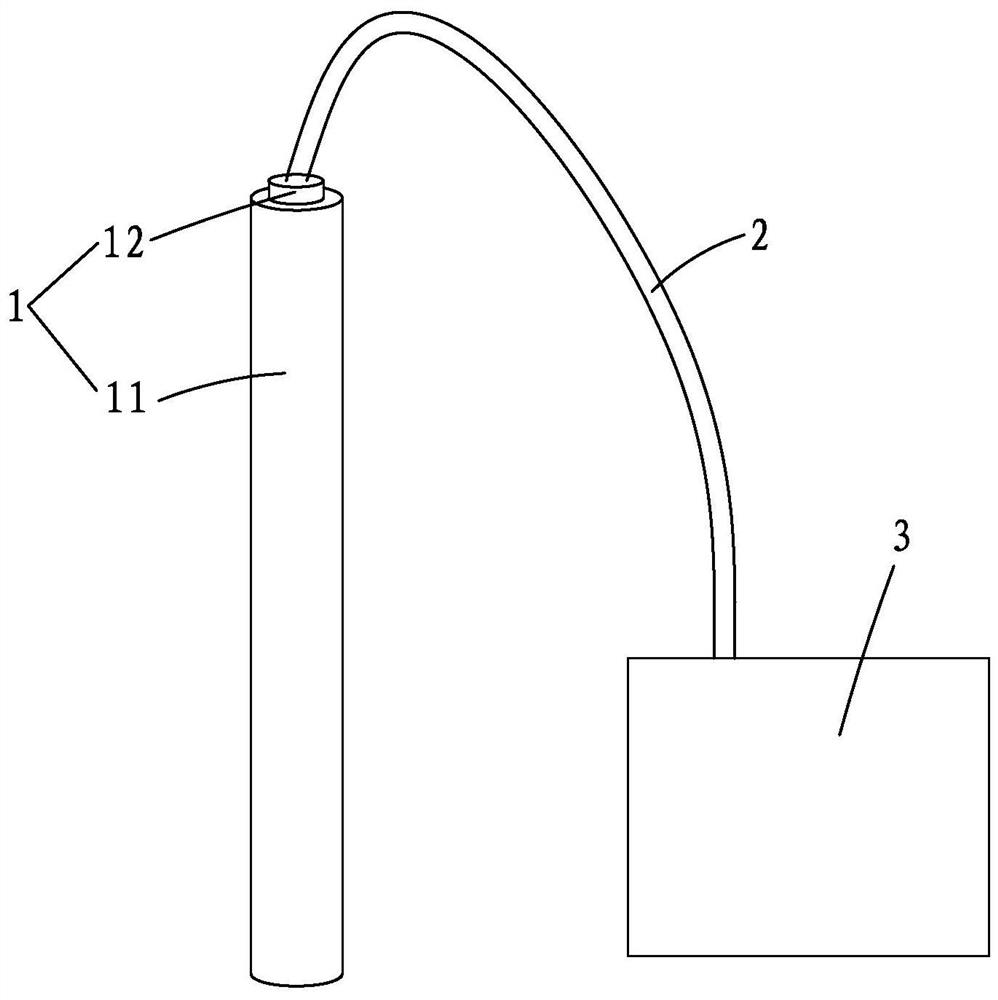
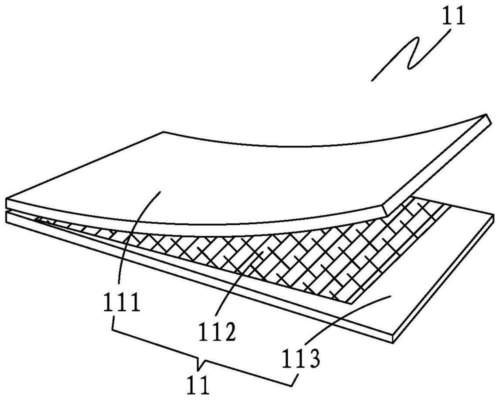
The invention provides a system for separating concrete with different strength grades in a beam-column joint core area and application. The beam-column joint core area further comprises a horizontally-arranged beam formwork and a plurality of beam ribs arranged in the beam formwork. The separating system comprises air inflation rods, an air pipeline, an air compressor, a fixing piece and a limiting frame. Each air inflation rod is in a long strip shape and comprises an air bag and an air nozzle, the air bags are connected with the air nozzles, the air nozzles are detachably connected with one end of an air pipeline, and the other end of the air pipeline is connected with the air compressor. The limiting frame is arranged on the beam-column joint core area, is positioned above the beam formwork and is used for separating and limiting the concrete with different strength grades; the multiple air inflation rods are inserted in parallel on the beam formwork on the outer side of the limiting frame, and are fixed to the beam ribs through fixing pieces; and the lengths of the air inflation rods are greater than the depth of the beam formwork. The system for separating the concrete with different strength grades in the beam-column joint core area has the advantages of simple on-site construction operation, reusability, cost saving and the like.

Description

【Technical field】 [0001] The invention relates to a concrete separation system of different strength grades in the core area of ​​a beam-column joint and its application. 【Background technique】 [0002] During the construction of concrete with different strength grades at the existing beam-column joints, the core joint area and the surrounding parts cannot be poured at the same time, and separation measures are required. At present, steel wire mesh is generally used to separate the low-grade concrete at the interface of beams and columns. This steel mesh is placed inside at one time without taking it out. First, high-grade concrete is poured. After pouring the concrete, vibrate the high-grade concrete first, and then vibrate the low-grade concrete. [0003] In modern society, high-rise and even super-high-rise buildings emerge in endlessly, resulting in the beam-column dimensions and depth and reinforcement of the ground floor are often larger than traditional buildings. T...

Claims


Application Information

Patent Timeline
Patent Type & Authority Applications(China)
IPC IPC(8): E04G21/02
CPCE04G21/02
Inventor 陈书明陈棋潘一帆林章凯肖木铎卢航添叶楗飞熊永健蔡晓东余福粟蔡星星
Owner 福建建工工程集团有限公司
Learn More