


Quick Research
Generate reliable direction feasibility study reports for your R&D in just a few steps.

Technical Q&A
Discover and master advanced knowledge NOW. Basics, ideas, possibilities, all at once.

Find Solutions
As an expert in R&D theories, this can generate solutions to your technical problems instantly.

Evaluate Feasibility
Analyze your overall solution with one click, know your potential R&D risks in advance.

Monitor Landscape
Get weekly tech updates, stay abreast of the latest tech innovations and key insights.
Energy-saving type glass curtain wall daylighting roof system with water guiding function
A glass curtain wall, energy-saving technology, applied in the direction of walls, building components, building insulation materials, etc., can solve the problems of water droplets not volatilizing in time, adverse effects of public living space, etc., to reduce adverse effects, improve connection safety, structure compact effect
- Summary
- Abstract
- Description
- Claims
- Application Information
AI Technical Summary
Problems solved by technology
Method used
Image

Examples
Embodiment 1
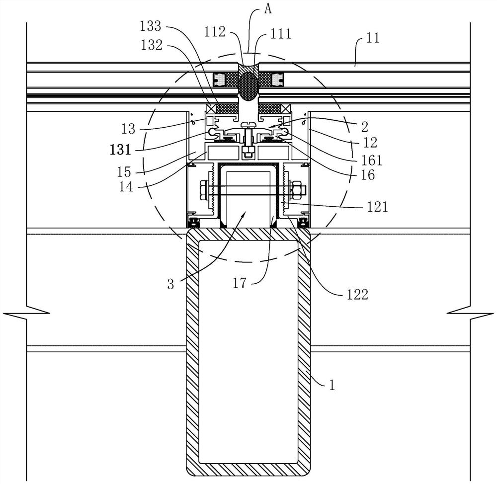
[0036] The embodiment of the present application discloses an energy-saving glass curtain wall daylighting roof system with water guiding function. Such as figure 1 , the energy-saving glass curtain wall lighting roof system with water guiding function includes square tube 1, grooved aluminum 12, attached frame 13, support 16 and glass 11.
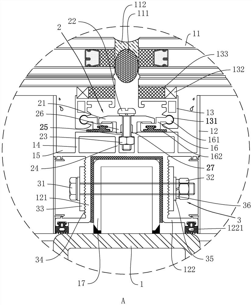
[0037] Such as figure 1 with figure 2 , the cross-section of the grooved aluminum 12 is U-shaped, and the bottom surface of the grooved aluminum 12 is vertically provided with two parallel aluminum plates 121. The side away from the groove aluminum 12 is vertically provided with ear plates 122, and the two ear plates 122 are away from each other. Sealing strips 1221 are clamped in the first glue grooves.
[0038] Such as figure 1 , the inner bottom surface of the grooved aluminum 12 is provided with an aluminum frame 14 of the same length as the aluminum frame 14. Internal height, the two sides of the aluminum frame 14 and the inner...
Embodiment 2
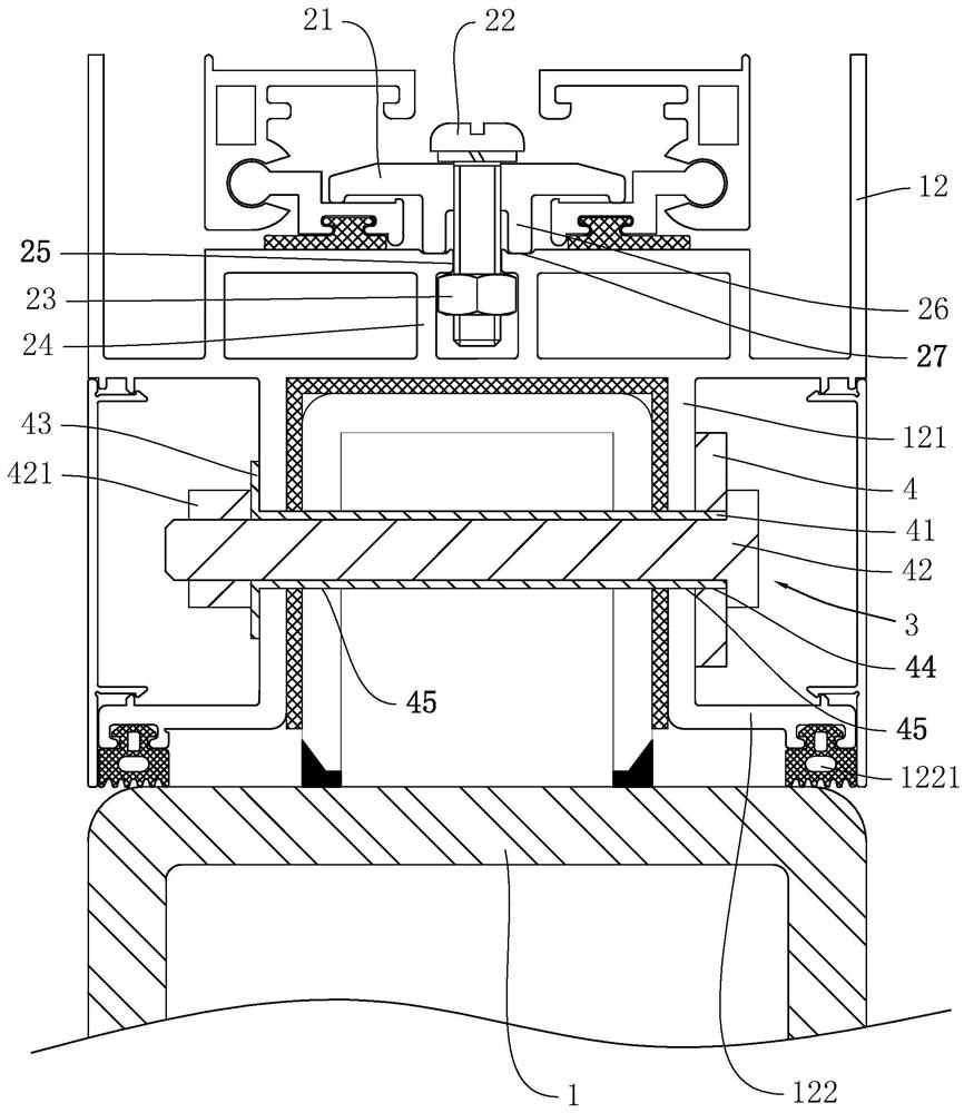
[0048] Such as image 3 The difference between this embodiment and Embodiment 1 is that the fixing member 3 includes a support plate 4, a second bolt 42 and a second nut 421, the side wall of the support plate 4 is vertically welded with a sleeve 41, and the support plate 4 is provided with The first through hole 44 communicating with the inside of the sleeve 41, the end of the sleeve 41 away from the support plate 4 is provided with a number of spacers 43 arranged equidistantly along the circumferential direction of the axis, and the aluminum plate 121 and the section steel 17 are provided with sleeves. The second through hole 45 corresponding to the barrel 41; when installing, the operator first passes the sleeve 41 through the second through hole 45, and makes the supporting plate 4 conflict with the corresponding aluminum plate 121, and then uses tools such as pliers to place each The limit piece 43 is bent and pressed against the corresponding side wall of the aluminum pl...
PUM
 Abstract
Description
Claims
Application Information
 - R&D Engineer
- R&D Manager
- IP Professional
- Industry Leading Data Capabilities
- Powerful AI technology
- Patent DNA Extraction
Browse by: Latest US Patents, China's latest patents, Technical Efficacy Thesaurus, Application Domain, Technology Topic, Popular Technical Reports.
© 2024 PatSnap. All rights reserved.Legal|Privacy policy|Modern Slavery Act Transparency Statement|Sitemap|About US| Contact US: help@patsnap.com