
Take-up and pay-off rack based on lifting type high-speed braiding machine

A high-speed knitting machine and wire take-up and pay-off technology, which is applied in the field of knitting machines, can solve the problems of occupying a large floor area, occupying a large area, and difficult daily management, etc., and achieve the goal of reducing the occupied area, reducing the occupied space, and improving stability. Effect

Active Publication Date: 2021-06-18
天长市海纳电气有限公司
View PDF5 Cites 0 Cited by
  • Summary
  • Abstract
  • Description
  • Claims
  • Application Information

AI Technical Summary

Problems solved by technology

[0002] The high-speed knitting machine can be used to weave a variety of items. When the high-speed knitting machine is in use, it needs to use the take-up and pay-off rack to make the wire of the knitting machine tight, so as to obtain a better weaving effect. Most of the existing pay-off racks are fixed on The ground will occupy a large area when multiple take-up and pay-off racks are used at the same time. At the same time, the dense arrangement on the plane will also affect daily management and maintenance. Problems that are difficult to manage day-to-day

Method used


Image

  • Take-up and pay-off rack based on lifting type high-speed braiding machine
  • Take-up and pay-off rack based on lifting type high-speed braiding machine
  • Take-up and pay-off rack based on lifting type high-speed braiding machine

Examples


Embodiment 1

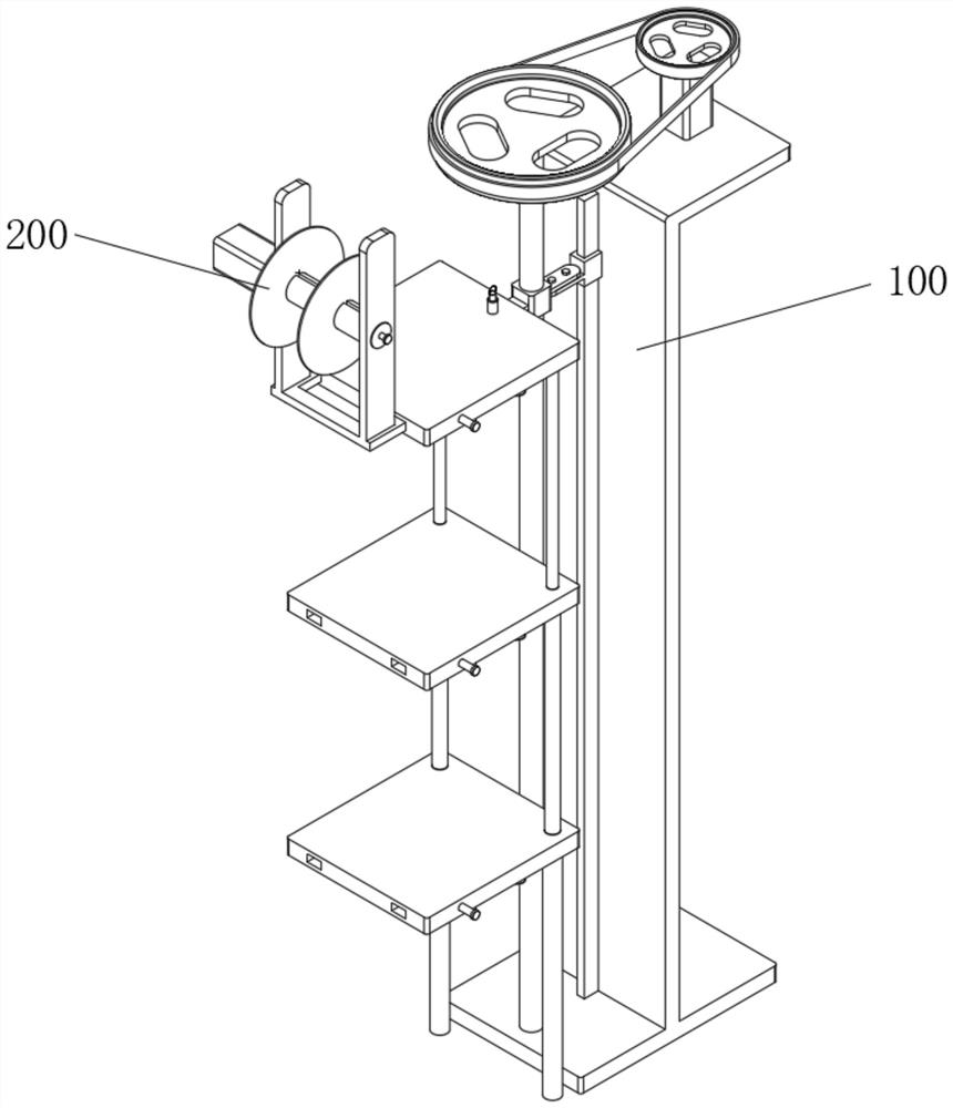
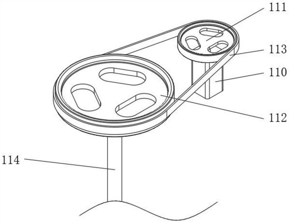
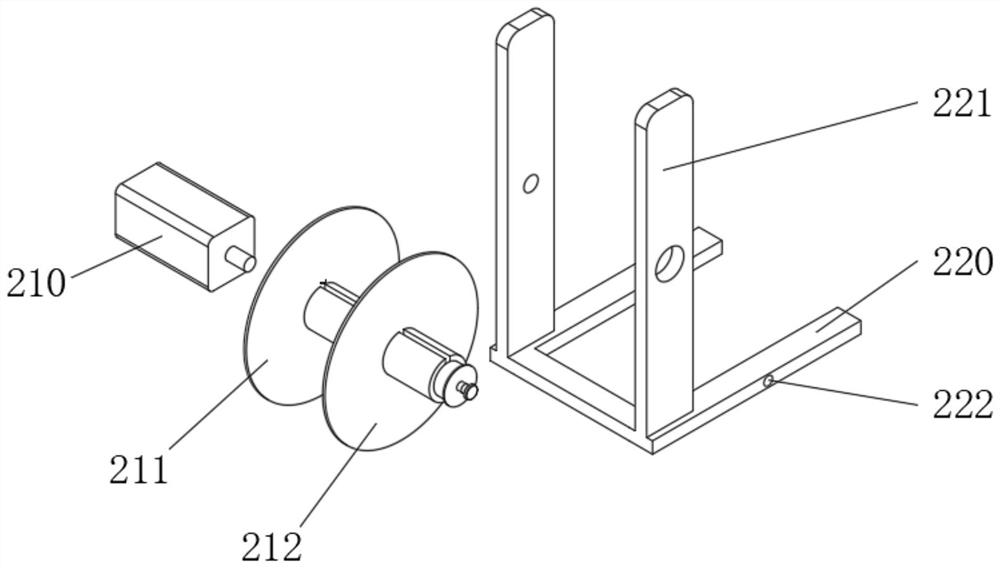
[0050] see Figure 1-Figure 11As shown, there is provided a take-up and pay-off frame based on a lifting type high-speed braiding machine, including a lifting device 100 and a taking-up and paying-off device 200 installed on the lifting device 100, and the lifting device 100 includes a lifting motor 110, preferably a stepping motor, as shown in the present invention As is well known to those skilled in the art, a stepper motor is a motor that converts electrical pulse signals into corresponding angular or linear displacements. Every time a pulse signal is input, the rotor rotates an angle or advances one step. The output angular displacement or linear displacement is proportional to the number of input pulses, and the rotational speed is proportional to the pulse frequency. A small pulley 111 is coaxially connected above the lifting motor 110. The side of the small pulley 111 is provided with a large pulley 112, the bottom of the large pulley 112 is coaxially connected with a ...


PUM


Abstract

The invention relates to the technical field of braiding machines, in particular to a take-up and pay-off rack based on a lifting type high-speed braiding machine. The rack comprises a lifting device and a take-up and pay-off device installed on the lifting device, wherein the lifting device comprises a lifting motor; a small belt wheel is coaxially connected to the upper portion of the lifting motor; a large belt wheel is arranged on the side face of the small belt wheel; a first lead screw is coaxially connected to the lower portion of the large belt wheel; a belt is arranged between the small belt wheel and the large belt wheel in a sleeving mode; a base is arranged below the lifting motor; the lifting motor is fixed to the base; the lead screw is in threaded connection with a threaded sleeve; and a mounting plate is fixed to the outer side of the threaded sleeve. The invention aims to solve the problems that a common take-up and pay-off rack is large in occupied ground area and difficult to manage daily.

Description

technical field [0001] The invention relates to the technical field of braiding machines, in particular, to a take-up and pay-off rack based on a lifting type high-speed braiding machine. Background technique [0002] The high-speed knitting machine can be used to weave a variety of items. When the high-speed knitting machine is in use, it needs to use the take-up and pay-off rack to make the wire of the knitting machine tight, so as to obtain a better weaving effect. Most of the existing pay-off racks are fixed on The ground will occupy a large area when multiple take-up and pay-off racks are used at the same time. At the same time, the dense arrangement on the plane will also affect daily management and maintenance. Problems that are difficult to manage on a day-to-day basis. Contents of the invention [0003] The object of the present invention is to provide a take-up and pay-off frame based on a lifting type high-speed braiding machine, so as to solve the problems rai...

Claims


Application Information

Patent Timeline
Patent Type & Authority Applications(China)
IPC IPC(8): D04C3/00D04C3/48
CPCD04C3/00D04C3/48
Inventor 闵志良
Owner 天长市海纳电气有限公司
Learn More