
Wireless unmanned aerial vehicle charging system with optical communication function

A wireless charging and unmanned aerial vehicle technology, applied in charging stations, electric vehicle charging technology, electric vehicles, etc., can solve the problems of mutual influence, severe attenuation, system performance degradation, etc., to avoid the influence of electromagnetic interference, low cost, The effect of simple structure

Pending Publication Date: 2021-06-18
ELECTRIC POWER RES INST OF GUANGXI POWER GRID CO LTD
View PDF7 Cites 1 Cited by
  • Summary
  • Abstract
  • Description
  • Claims
  • Application Information

AI Technical Summary

Problems solved by technology

Generally speaking, in the environment of the existing ICPT system, there is usually a certain intensity of electromagnetic interference. Although the interference limit can be reduced under the existing technology, due to the complex and changeable environment, and through the wireless in the electromagnetic induction mode The communication method determines the characteristics of low-energy and short-distance communication of its signal transmission, and its attenuation is very severe in the process of air transmission. The influence of electromagnetic interference on it must be considered, which increases the complexity of system design.
In addition, it is necessary to adopt the method of simultaneous transmission of electromagnetic induction mode signals and magnetic coupling induction energy. For the separate transmission of power and signals, the transmission equipment designed by many researchers is cumbersome and complicated, and the power and signals affect each other, resulting in system performance degradation.
However, the transmission of power and signals in the same channel also has problems such as the power transmission power drops and the signal transmission is seriously affected.

Method used


Image

  • Wireless unmanned aerial vehicle charging system with optical communication function
  • Wireless unmanned aerial vehicle charging system with optical communication function
  • Wireless unmanned aerial vehicle charging system with optical communication function

Examples


Embodiment

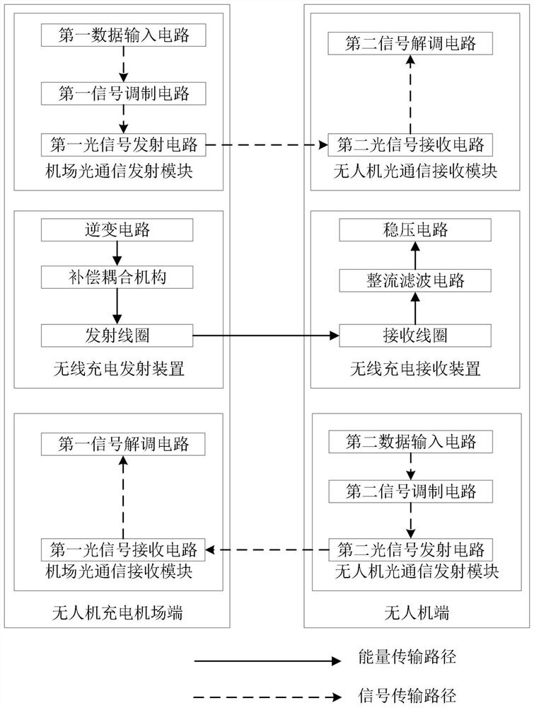
[0029] see figure 1 , figure 2 and image 3 , figure 1 It is a schematic diagram of the structural composition of a wireless charging system for a drone with an optical communication function in an embodiment of the present invention; figure 2 It is a schematic circuit diagram of an optical signal transmitting circuit in an embodiment of the present invention; image 3 It is a schematic circuit diagram of the optical signal receiving circuit in the embodiment of the present invention.

[0030] Such as Figure 1-Figure 3 As shown, a UAV wireless charging system with optical communication function, the method includes: a UAV charging airport terminal and a UAV terminal; wherein, the UAV charging airport terminal and the UAV The terminal is wirelessly connected based on optical communication; the UAV charging airport terminal includes an airport optical communication transmitting module, a wireless charging transmitting device and an airport optical communication receiving...


PUM


Abstract

The invention discloses a wireless unmanned aerial vehicle charging system with an optical communication function. The system comprises an unmanned aerial vehicle charging airport end and an unmanned aerial vehicle end, wherein the unmanned aerial vehicle charging airport end comprises an airport optical communication transmitting module, a wireless charging transmitting device and an airport optical communication receiving module; the unmanned aerial vehicle end comprises an unmanned aerial vehicle optical communication receiving module, a wireless charging receiving device and an unmanned aerial vehicle optical communication transmitting module; the airport optical communication transmitting module of the unmanned aerial vehicle airport end sends an optical signal to the unmanned aerial vehicle optical communication receiving module of the unmanned aerial vehicle end, and the unmanned aerial vehicle optical communication transmitting module of the unmanned aerial vehicle end sends an optical signal to the airport optical communication receiving device of the unmanned aerial vehicle charging airport end; and a wireless charging transmitting device of the unmanned aerial vehicle charging airport end sends charging energy to the unmanned aerial vehicle, and the unmanned aerial vehicle end receives the charging energy based on a wireless charging receiving device. According to embodiments of the invention, signal transmission is realized through a simple structure, and the influence of electromagnetic interference on the optical signal in a transmission process is avoided.

Description

technical field [0001] The invention relates to the technical field of wireless charging, in particular to a wireless charging system for a drone with an optical communication function. Background technique [0002] In order to solve the insufficient endurance of drone inspections, the traditional wired charging method has exposed shortcomings such as poor flexibility, low reliability, and low autonomy. In response to these problems, the wireless charging of UAVs is becoming more and more widely used. The wireless charging of drones usually adopts inductive coupling power transfer ICPT (inductive coupling power transfer). During the wireless charging process of drones, it usually needs to communicate with the charging airport. [0003] The existing energy and signal synchronous transmission technology either constructs a pair of coupling coils separately for signal transmission, or intercepts a part of the energy coupling coil as a signal coupling coil for signal transmissi...

Claims


Application Information

Patent Timeline
Patent Type & Authority Applications(China)
IPC IPC(8): B60L53/12H04B10/60H04B10/50
CPCB60L53/12H04B10/60H04B10/50Y02T10/70Y02T10/7072Y02T90/16Y02T90/14
Inventor 奉斌俞小勇陈绍南陈千懿高立克秦丽文吴丽芳李克文欧世锋欧阳健娜黄伟翔
Owner ELECTRIC POWER RES INST OF GUANGXI POWER GRID CO LTD
Learn More