
Intelligent welding robot

A welding robot and welding mechanism technology, applied in welding equipment, auxiliary welding equipment, welding/cutting auxiliary equipment, etc., can solve the problems of single clamping device, deformation of welding parts, single function, etc.

Inactive Publication Date: 2021-06-18
NANJING FORESTRY UNIV
View PDF0 Cites 1 Cited by
  • Summary
  • Abstract
  • Description
  • Claims
  • Application Information

AI Technical Summary

Problems solved by technology

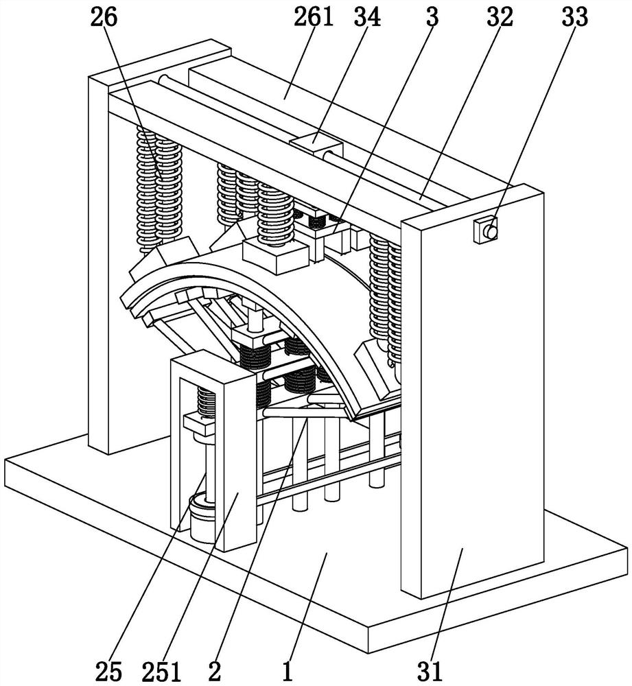
[0005] The invention provides an intelligent welding robot, which can solve the following problems in the welding process: a. The traditional welding method, one is to fix the welding torch and move the clamped welding parts to realize welding. When the workpiece is moved, it will cause problems such as welding deviation or virtual welding. The second is to fix the clamped weldment and move the welding torch. This method makes different clamping devices required for different weldments and cannot achieve the same The clamping device is suitable for welding parts of various specifications, which has certain limitations; b. When the traditional arc-shaped surface welding parts are welded, when the welding parts are clamped and fixed by the clamping device, when the clamping force is too large When it is used, it is easy to cause deformation of the weldment, and it is easy to scratch the surface of the weldment, and the clamping device for the arc-shaped surface weldment is relatively simple, which cannot realize the clamping of the weldment for different arcs, and the function is single

Method used


Image

  • Intelligent welding robot
  • Intelligent welding robot
  • Intelligent welding robot

Examples


Embodiment Construction

[0028] Embodiments of the present invention will be described below with reference to the drawings. In the process, in order to ensure the clarity and convenience of illustration, we may exaggerate the width of the lines or the size of the constituent elements in the diagram.

[0029]In addition, the following terms are defined based on the functions in the present invention, and may be different according to the user's or operator's intention or practice. Therefore, these terms are defined based on the entire content of this specification.

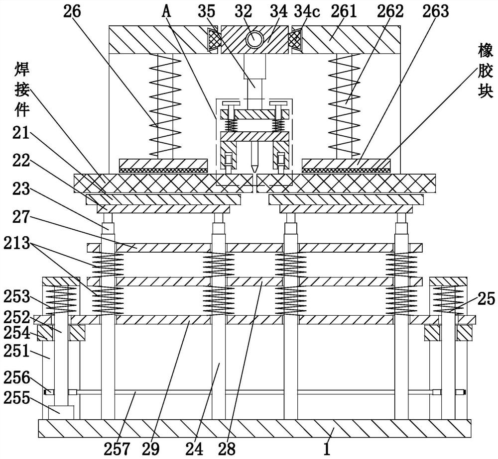
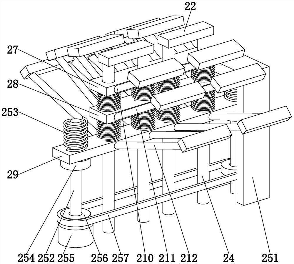
[0030] Such as Figure 1 to Figure 7 As shown, an intelligent welding robot includes a base 1, a clamping and fixing mechanism 2, and a mobile welding mechanism 3. The upper end of the base 1 is provided with a clamping and fixing mechanism 2, and the top of the clamping and fixing mechanism 2 is set There is mobile welding mechanism 3; among them:

[0031] The clamping and fixing mechanism 2 includes a support plate 21, a support bloc...


PUM


Abstract

The invention provides an intelligent welding robot. The intelligent welding robot comprises a base, a clamping and fixing mechanism and a mobile welding mechanism. The intelligent welding robot can solve the following problems in the welding process: (a) according to a traditional welding method, in one case, due to the fact that welding is achieved by fixing a welding torch and enabling clamped weldments to move, the weldments may deviate when moving, resulting in welding misalignment, false welding and other problems; and in the other case, due to the fact that welding is achieved by fixing the clamped weldments and enabling the welding torch to move, the different weldments require different clamping devices, and the purpose that the same clamping device is applicable to the weldments of various specifications can not be achieved, resulting in certain limitations; and (b) during traditional welding of weldments with arc-shaped surfaces, due to the fact that the weldments are clamped and fixed through the clamping devices, the weldments are prone to be deformed and the surfaces of the weldments are prone to be scratched when the clamping force is too large; and in addition, the clamping devices for the weldments with the arc-shaped surfaces are relatively simplistic, and incapable of achieving the clamping of the weldments with different arcs.

Description

technical field [0001] The invention relates to the field of welding technology, in particular to an intelligent welding robot. Background technique [0002] Welding: also known as welding and welding, is a manufacturing process and technology for joining metal or other thermoplastic materials such as plastics by means of heating, high temperature or high pressure. According to the characteristics of its process, it can be divided into three categories: fusion welding, pressure welding and brazing. Fusion welding is to heat the workpieces to be joined to make them partially melt to form a molten pool. After the molten pool is cooled and solidified, it can be joined. If necessary, welding can be added It is suitable for the welding process of various metals and alloys without pressure; pressure welding is the welding process that must exert pressure on the weldment, which belongs to the processing of various metal materials and some metal materials; The metal material with l...

Claims


Application Information

Patent Timeline
Patent Type & Authority Applications(China)
IPC IPC(8): B23K37/04B23K37/02B23K37/00
CPCB23K37/00B23K37/0252B23K37/0426
Inventor 吴东洋
Owner NANJING FORESTRY UNIV
Learn More