Stamping die fixing and limiting type insert

A stamping die and fixing block technology, applied in the field of die manufacturing, can solve the problems of lack of sealing equipment, prolonged die forming time, loss of compressed air heat, etc., to solve the problem of uneven internal stress, shorten the time of thermoforming, structural science reasonable effect

Pending Publication Date: 2021-06-18
湖北法科拉精密制造股份有限公司
View PDF0 Cites 0 Cited by
  • Summary
  • Abstract
  • Description
  • Claims
  • Application Information

AI Technical Summary

Problems solved by technology

[0003] The present invention provides a fixed-limiting insert for a stamping die, which can effectively solve the problem of poor stability in the above-mentioned background technology, which often causes the center of the mold to deviate during stamping, causing burrs on the edge of the product, thereby reducing product production. The quality increases the economic cost, the uneven internal stress of the mold reduces the hardness of the product, and it is easy to be brittle during the collision process. There is no sealing equipment, which leads to excessive loss of compressed air, cooling air, hot air, etc., which affects the thermoforming module. Poor quality, poor heat insulation effect, easy to dissipate the heat inside the mold, prolong the molding time of the mold, etc.

Method used


Image

  • Stamping die fixing and limiting type insert
  • Stamping die fixing and limiting type insert
  • Stamping die fixing and limiting type insert

Examples


Embodiment Construction

[0018] The preferred embodiments of the present invention will be described below in conjunction with the accompanying drawings. It should be understood that the preferred embodiments described here are only used to illustrate and explain the present invention, and are not intended to limit the present invention.

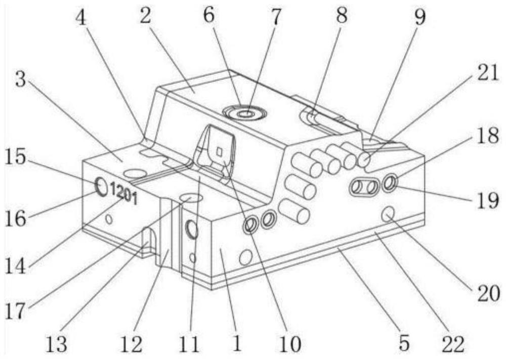
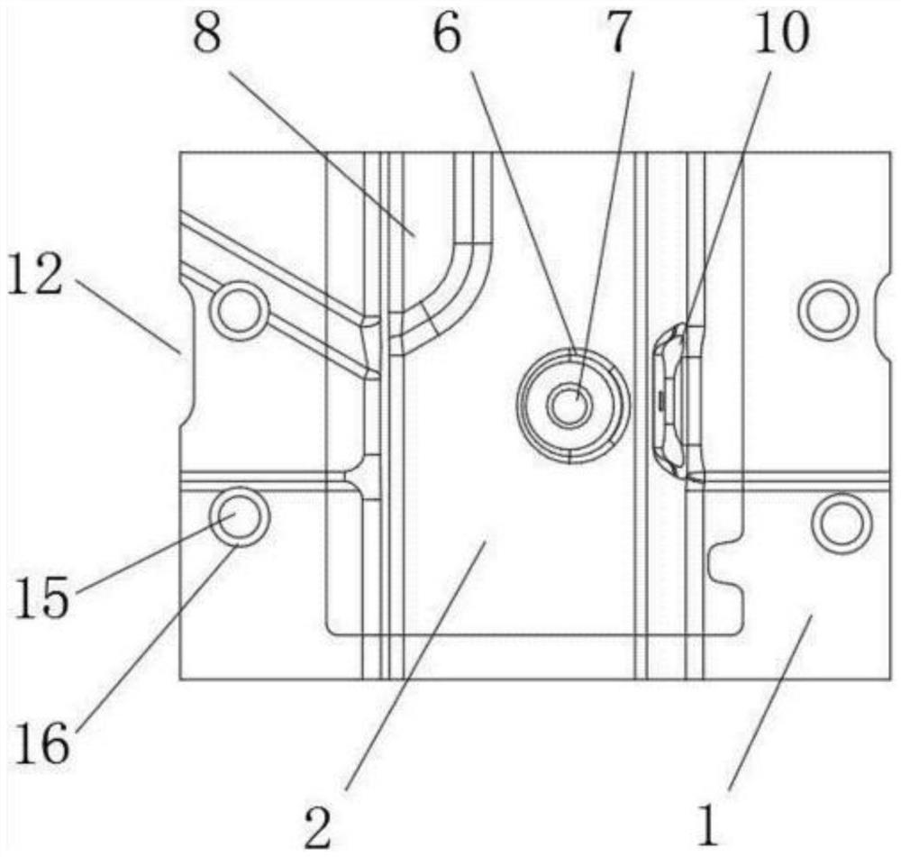
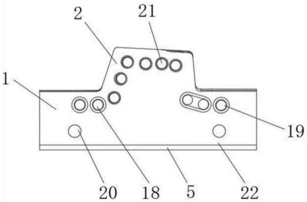
[0019] Example: such as Figure 1-6 As shown, the present invention provides a technical solution, a stamping die fixed limit insert, including insert body 1, movable mold 2, fixed mold 3, movable mold backing plate 4, fixed mold bottom plate 5, positioning ring 6 , nozzle 7, fixed block 8, guide post 9, main channel bushing 10, hot runner plate 11, limit groove 12, fixed groove 13, digital mark 14, compressed gas through hole 15, sealing rubber ring 16, heating Device hole 17, fixing screw hole 18, internal thread 19, cooling air passage hole 20, heating rod 21 and heat insulation plate 22, a movable mold 2 is arranged above the insert body 1, and a fixed mold 3 is...


PUM


Abstract

The invention discloses a stamping die fixing and limiting type insert. The stamping die fixing and limiting type insert comprises a positioning ring, a limiting groove, a sealing rubber ring, a fixing screw hole, a heating rod and a heat insulation plate, wherein the limiting groove is formed in the lower portion of the positioning ring, a fixing screw hole is formed in the right side of the sealing rubber ring, and the heat insulation plate is arranged below the heating rod. According to the stamping die fixing and limiting type insert, the structure is scientific and reasonable, using is safe and convenient, and the positioning ring is arranged so that the liquid can be prevented from deviating during pouring; the limiting groove is formed so that the phenomenon that the insert deviates when a die is stamped can be prevented; the sealing rubber ring is arranged so that gas can be prevented from entering, leakage is avoided, and gas in the die is uniformly distributed; the fixing screw hole is formed, so that fixing of the die and connection between the die and other objects are facilitated; the heating rod is arranged, so that the interior of the die is heated more uniformly, and the hardness of a product is improved; and the heat insulation plate is arranged, so that the heat forming time is shortened, and the problem of non-uniform internal stress of the product is solved.

Description

technical field [0001] The invention relates to the technical field of mold manufacturing, in particular to a fixed and position-limiting insert for a stamping mold. Background technique [0002] Or it is not easy to process to make inserts. With the development of industry, people's requirements for mold inserts are also increasing. The insert is a part that can be replaced by the middle finger of the mold and fixedly embedded in the mold cavity. Generally, it is in the part that is easy to wear. The fixation of the mold insert and its cooling and tempering process have become a concern, but most of the existing molds on the market The cost of the insert is not only high, but also poor in stability. As a result, the center of the mold often deviates during stamping, causing burrs on the edge of the product, thereby reducing the production quality of the product and increasing the economic cost. When the cooling air is cooled and tempered, due to the uneven entry of the coo...

Claims


Application Information

Patent Timeline
IPC IPC(8): B22D18/02B22D27/04
CPCB22D18/02B22D27/04
Inventor 何浩玮
Owner 湖北法科拉精密制造股份有限公司
Why Eureka
Try Eureka