A liquid mixing treatment equipment
A processing equipment and mixing processing technology, applied in mixers, mixing methods, mixers with rotary stirring devices, etc., can solve the problems of reduced overall coordination of equipment, low mixing efficiency, power waste, etc.
- Summary
- Abstract
- Description
- Claims
- Application Information
AI Technical Summary
Problems solved by technology
Method used
Image
Examples
specific Embodiment approach 1
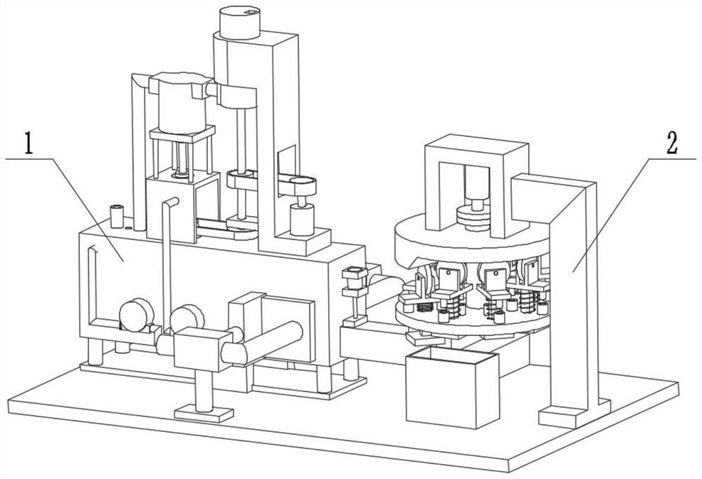
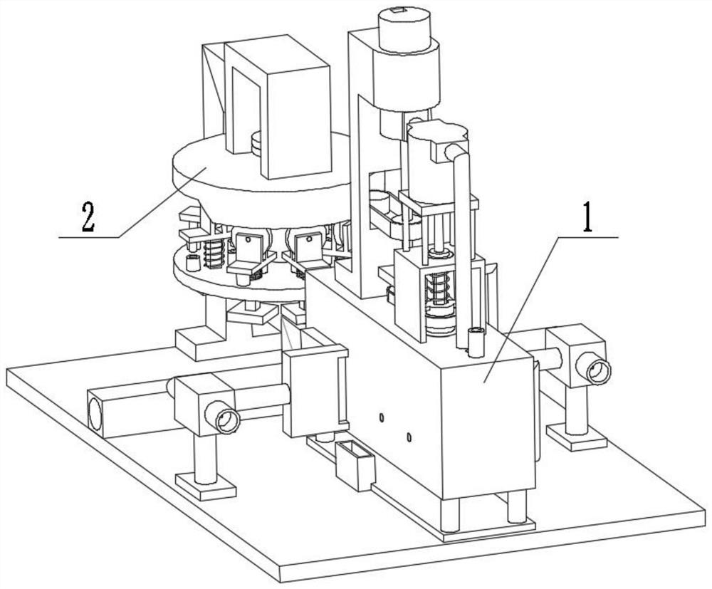
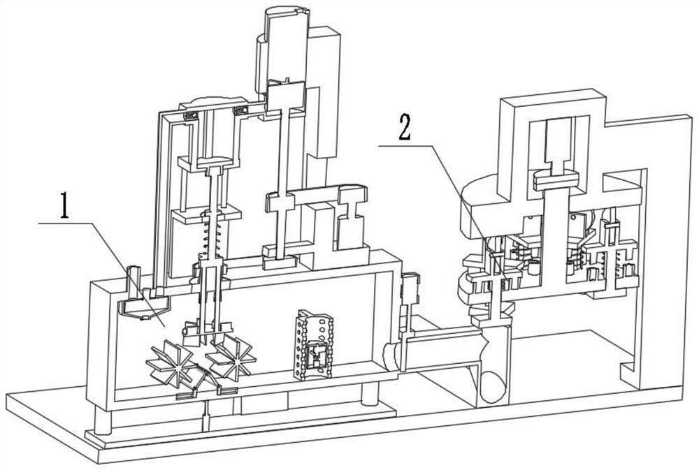
[0029] Combine below figure 1 , figure 2 , image 3 , Figure 4 , Figure 5 , Image 6 , Figure 7 , Figure 8 , Figure 9 , Figure 10 , Figure 11 , Figure 12 , Figure 13 , Figure 14 , Figure 15 , Figure 16 Illustrating this embodiment, the present invention relates to a mixing device, more specifically, a liquid mixing and processing device, including a mixing processing mechanism 1 and an iron removing mechanism 2. The equipment can ensure the activation of the original liquid, the equipment can perform stirring, and the equipment can The stirring power is used to complete the pre-mixing of the raw materials, and at the same time, the purification of the air and the cooling of the transmission part are completed. The equipment can filter and complete self-cleaning, and the equipment can remove iron.
[0030] The mixing processing mechanism 1 is connected with the iron removing mechanism 2 .
specific Embodiment approach 2
[0031] Combine below figure 1 , figure 2 , image 3 , Figure 4 , Figure 5 , Image 6 , Figure 7 , Figure 8 , Figure 9 , Figure 10 , Figure 11 , Figure 12 , Figure 13 , Figure 14 , Figure 15 , Figure 16This embodiment will be described. This embodiment will further describe Embodiment 1. The mixing processing mechanism 1 includes a base 1-1, a base 1-2, a mixing box leg 1-3, a connecting pipe 1-4, a mixing box 1-5. Connecting tube seat 1-6, filter plate groove 1-7, filter plate 1-8, bellows 1-9, connecting pipe I1-10, first stock solution inlet tube 1-11, second stock solution inlet tube 1 -12, bearing seat 1-13, transfer box 1-14, air inlet pipe 1-15, liquid inlet pipe 1-16, support seat 1-17, raw material barrel 1-18, raw material inlet 1-19, rotating shaft 1- 20. Pulley 1-21, belt 1-22, motor pulley 1-23, motor 1-24, pulley I1-25, mixing liquid pipe 1-26, iron removal opening 1-27, collection box 1-28, extrusion Pressure box 1-29, extrusion pipe ...
specific Embodiment approach 3
[0032] Combine below figure 1 , figure 2 , image 3 , Figure 4 , Figure 5 , Image 6 , Figure 7 , Figure 8 , Figure 9 , Figure 10 , Figure 11 , Figure 12 , Figure 13 , Figure 14 , Figure 15 , Figure 16 This embodiment will be described. This embodiment will further describe Embodiment 1. The iron removing mechanism 2 includes a curved arm support 2-1, an electromagnetic plate 2-2, a sliding square column 2-3, a square hole 2-4, a compression Spring 2-5, pulley seat 2-6, pulley 2-7, first step 2-8, inclined plane 2-9, second step 2-10, fixed plate 2-11, coupling I2-12, stepper Motor 2-13, motor support base 2-14, socket 2-15, plug 2-16, shaft rotating disk 2-17, arm support 2-1 is connected with base 1-1, electromagnetic plate 2-2 is connected with The sliding square column 2-3 is connected, the sliding square column 2-3 is slidably connected with the square hole 2-4, the square hole 2-4 is arranged on the belt shaft rotating plate 2-17, and the comp...
PUM
 Abstract
Description
Claims
Application Information
 - R&D
- Intellectual Property
- Life Sciences
- Materials
- Tech Scout
- Unparalleled Data Quality
- Higher Quality Content
- 60% Fewer Hallucinations
Browse by: Latest US Patents, China's latest patents, Technical Efficacy Thesaurus, Application Domain, Technology Topic, Popular Technical Reports.
© 2025 PatSnap. All rights reserved.Legal|Privacy policy|Modern Slavery Act Transparency Statement|Sitemap|About US| Contact US: help@patsnap.com


