
Weak current amplifying circuit and sensor system

A weak current and amplifying circuit technology, applied to amplifiers with multiple amplifying elements, improving amplifiers to reduce temperature/power supply voltage changes, etc., can solve problems such as large differences in input impedance and large differences in output effects, and achieve Easy to personalize design, good common mode rejection ability, easy to adjust the effect

Active Publication Date: 2021-06-15
SHENZHEN GRADUATE SCHOOL TSINGHUA UNIV
View PDF4 Cites 1 Cited by
  • Summary
  • Abstract
  • Description
  • Claims
  • Application Information

AI Technical Summary

Problems solved by technology

The input impedance of these back-end devices is very different. If the output signal is not specially processed, the output effect will be very different in these different applications.

Method used


Image

  • Weak current amplifying circuit and sensor system
  • Weak current amplifying circuit and sensor system
  • Weak current amplifying circuit and sensor system

Examples


Embodiment Construction

[0035] Embodiments of the present invention will be described in detail below. It should be emphasized that the following description is only exemplary and not intended to limit the scope of the invention and its application.

[0036] It should be noted that when an element is referred to as being “fixed” or “disposed on” another element, it may be directly on the other element or be indirectly on the other element. When an element is referred to as being "connected to" another element, it can be directly connected to the other element or indirectly connected to the other element. In addition, the connection can be used for fixation as well as for coupling or communication.

[0037] It is to be understood that the terms "length", "width", "top", "bottom", "front", "rear", "left", "right", "vertical", "horizontal", "top" , "bottom", "inner", "outer" and other indicated orientations or positional relationships are based on the orientations or positional relationships shown in ...


PUM


Abstract

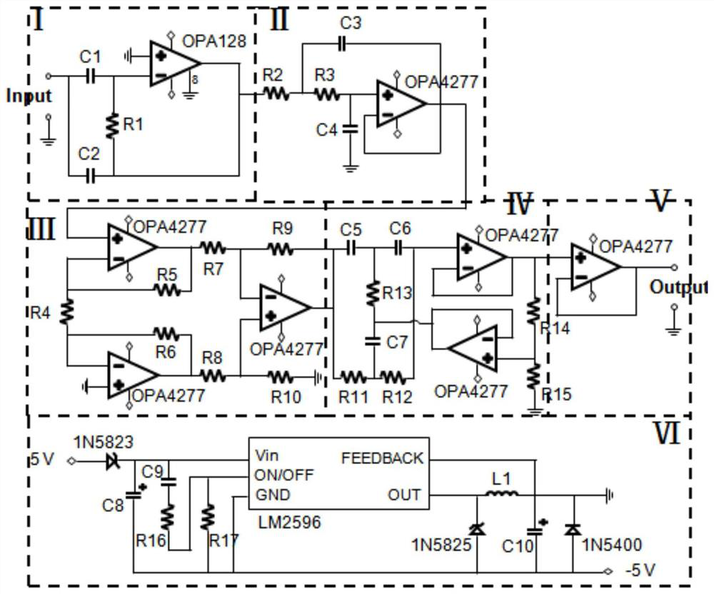
The invention relates to a weak current amplifying circuit and a sensor system. The weak current amplifying circuit is provided with a two-stage amplifying structure and a two-stage filtering structure which are arranged in a crossed mode; the weak current amplifying circuit comprises a charge amplifier, a first-stage filter, a second-stage amplifier and a band elimination filter which are connected, and the charge amplifier converts weak current into amplified voltage output; the first-stage filter performs at least one of low-pass filtering, band-pass filtering and high-pass filtering on the voltage output by the charge amplifier, the second-stage amplifier performs a second-stage amplification process, the second-stage amplifier is provided with two stages of differential amplifier circuits, wherein the preceding stage amplifies a differential-mode input signal in an in-phase differential input mode, and plays a role in following the common-mode input signal so as to improve the amplitude ratio of the differential-mode signal and the common-mode signal which are sent to the rear stage, and is used for filtering 50Hz power frequency noise interference. The weak current amplifying circuit overcomes the problems of strong noise, power frequency interference, output end impedance mismatching, operational amplifier output saturation and the like of the conventional amplifying circuit.

Description

technical field [0001] The invention relates to a weak current amplifying circuit and a sensor system with the weak current amplifying circuit. Background technique [0002] In practical applications, it is often faced with the precise measurement of weak signals such as micro-light intensity, micro-magnetic field, micro-displacement, micro-pressure, and micro-temperature difference. Sensing of these physical quantities to be measured is often achieved using photoelectric sensors, magnetometers, displacement sensors, piezoelectric sensors, and pyroelectric sensors. Since the signal to be measured is very weak, the output current directly obtained by the sensor is often only in the order of pA to nA. Such a weak current signal is very difficult to process, and it is easily overwhelmed by noise during line transmission, and often requires further amplification and filtering before it can be displayed on the meter head of the instrument. Therefore, the amplification of pA-nA ...

Claims


Application Information

Patent Timeline
Patent Type & Authority Applications(China)
IPC IPC(8): H03F3/42H03F1/30
CPCH03F3/42H03F1/30
Inventor 董瑛韩留洋王晓浩
Owner SHENZHEN GRADUATE SCHOOL TSINGHUA UNIV
Learn More