Rotor assembly and self-starting permanent magnet synchronous reluctance motor

A component and rotor technology, applied in the direction of synchronous machine parts, electric components, magnetic circuit rotating parts, etc., can solve the problems of motor system efficiency reduction, permanent magnet torque reduction, motor performance reduction, etc., to increase the d-axis Effect of reluctance, increasing reluctance torque, improving performance and efficiency

Active Publication Date: 2022-06-24
GREE ELECTRIC APPLIANCES INC
View PDF7 Cites 0 Cited by
  • Summary
  • Abstract
  • Description
  • Claims
  • Application Information

AI Technical Summary

Problems solved by technology

[0003] Traditional permanent magnet motors and self-starting permanent magnet synchronous reluctance motors require a driver to start and control the operation, which is costly and complicated to control, and the driver occupies a part of the loss, which reduces the efficiency of the entire motor system
[0004] The Chinese invention patent with the patent publication number CN107994698A provides a self-starting permanent magnet synchronous reluctance motor to reduce the cost of permanent magnets. However, in this patent, the magnetic flux concentrates along the direction of the q-axis, which reduces the magnetic flux in the direction of the d-axis. Reduced magnetic torque and reduced motor performance

Method used


Image

  • Rotor assembly and self-starting permanent magnet synchronous reluctance motor
  • Rotor assembly and self-starting permanent magnet synchronous reluctance motor
  • Rotor assembly and self-starting permanent magnet synchronous reluctance motor

Examples


Embodiment Construction

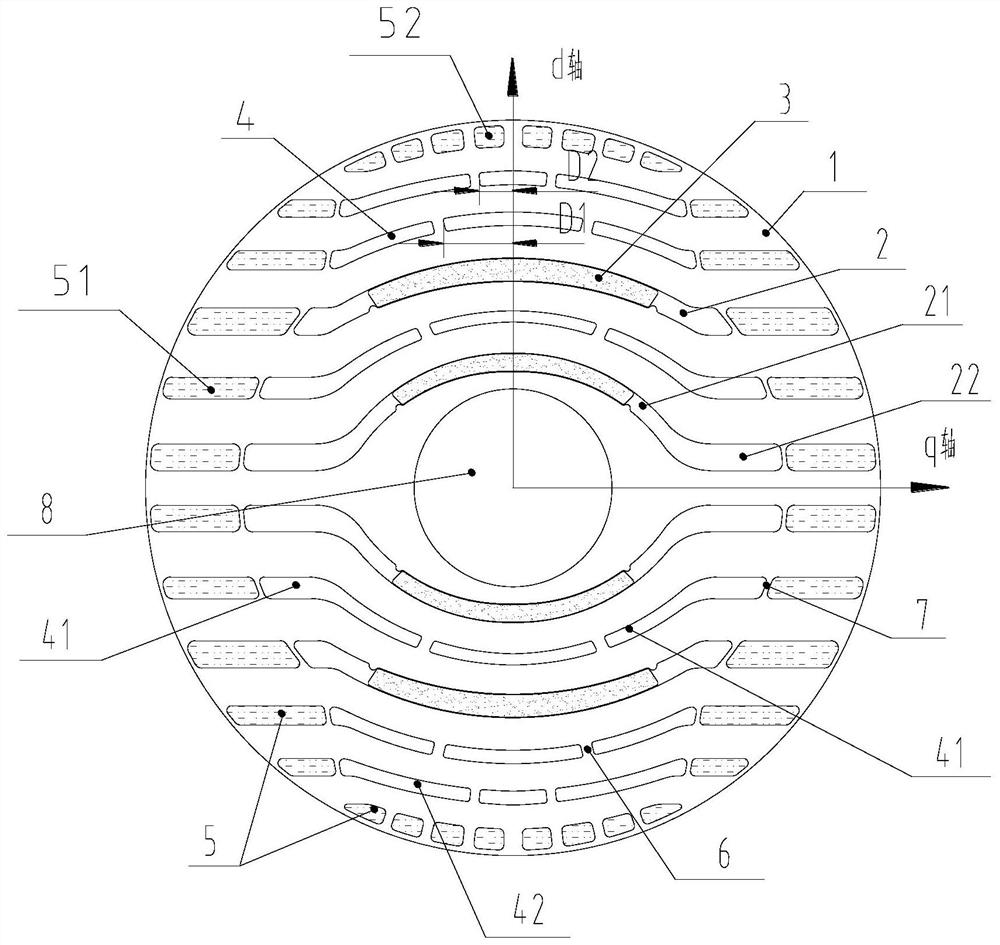
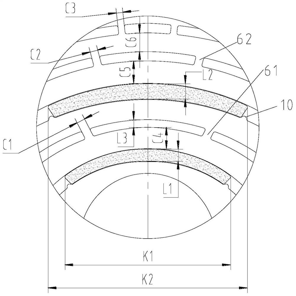
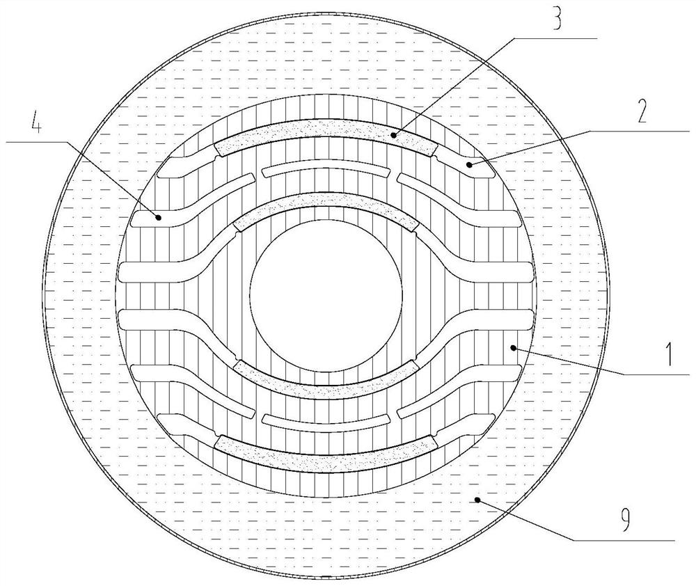
[0034] see in combination Figure 1 to Figure 3 As shown, according to the embodiment of the present application, the rotor assembly includes a rotor core 1, and on a cross section of the rotor core 1, the rotor core 1 is provided with a shaft hole 8, a mounting slot 2, a magnetic barrier slot 4 and a plurality of mouse The cage slot 5, the squirrel cage slot 5 is distributed on the outer circumference of the rotor core 1, the permanent magnet 3 is installed in the installation slot 2, the magnetic barrier slot 4 includes the outer magnetic barrier slot 42, and the outer magnetic barrier slot 42 is installed at the outermost layer. On the radially outer side of the slot 2 , the outer magnetic barrier slots 42 are at least two layers, and at least two second magnetic bridges 61 are provided on each outer magnetic barrier slot 42 .

[0035] In the rotor assembly of the present embodiment, at least two outer magnetic barrier layers 42 are arranged radially outside the outermost m...


PUM


Abstract

The present application provides a rotor assembly and a self-starting permanent magnet synchronous reluctance motor. The rotor assembly includes a rotor core (1), on the cross section of the rotor core (1), the rotor core (1) is provided with a mounting slot (2), a magnetic barrier slot (4) and a plurality of squirrel cage slots ( 5), the squirrel cage slots (5) are distributed on the outer circumference of the rotor core (1), the permanent magnets (3) are installed in the installation slots (2), and the magnetic barrier slots (4) include the outer magnetic barrier slots (42), The outer layer magnetic barrier groove (42) is positioned at the radially outside of the outermost layer installation groove (2), and the outer layer magnetic barrier groove (42) is at least two layers, and each layer of outer layer magnetic barrier groove (42) is provided with at least two a second magnetic bridge (61). According to the rotor assembly of the present application, the reluctance torque and the permanent magnet torque of the motor can be increased at the same time, and the performance and efficiency of the motor can be improved.

Description

technical field [0001] The present application relates to the technical field of motors, and in particular to a rotor assembly and a self-starting permanent magnet synchronous reluctance motor. Background technique [0002] The self-starting permanent magnet synchronous reluctance motor combines the structural characteristics of the induction motor and the synchronous permanent magnet reluctance motor. The torque generated by the squirrel cage induction realizes the starting, and the permanent magnet is realized by the difference between the rotor d and q axis magnetic flux and the torque generated by the permanent magnet. Speed ​​operation, can be directly connected to the power supply to achieve start-up operation. The self-starting permanent magnet synchronous reluctance motor can use the reluctance torque to increase the output torque of the motor. Compared with the self-starting permanent magnet motor, the amount of permanent magnets is reduced and the cost is reduced; ...

Claims


Application Information

Patent Timeline
Patent Type & Authority Patents(China)
IPC IPC(8): H02K1/27H02K1/272H02K21/02
CPCH02K1/27H02K1/272H02K21/02
Inventor 史进飞肖勇陈彬张志东李霞
Owner GREE ELECTRIC APPLIANCES INC
Why Eureka
Try Eureka