A commutation transformer phase closing excitation inrush current suppression method based on bias magnet simulation

A technology for phase selection and closing and magnetizing inrush current, which can be used in emergency protection circuit devices for limiting overcurrent/overvoltage, AC network circuits, power transmission AC networks, etc. , large excitation inrush current and other problems, to achieve the effect of good economy and reduce the risk of commutation failure

Active Publication Date: 2022-06-28
ELECTRIC POWER RES INST OF STATE GRID ANHUI ELECTRIC POWER +1
View PDF0 Cites 0 Cited by
  • Summary
  • Abstract
  • Description
  • Claims
  • Application Information

AI Technical Summary

Problems solved by technology

The series combination resistance measure is limited by the selection of the closing resistance value and the resistance input time, and sometimes the closing inrush current is relatively high; after adopting the phase-selection closing measure, since the phase-selection closing operation depends on the fixed closing phase, that is, Y The three phases of the bridge converter rheology switch on respectively at their voltage peaks, the first closing phase of the D bridge converter switches on at its voltage peak value, and the other two phases close 1 / 4 cycle behind the first closing phase. When considering the commutation The original closing phase may not meet the closing requirements due to the different residual magnetism values ​​after switching off and the mechanical stability of the circuit breaker, which may cause a large excitation inrush current
Therefore, when considering the maintenance and switching operation mode of the HVDC transmission system, the above-mentioned measures have a limited effect of suppressing the excitation inrush current of the converter transformer, and the suppression measures of the excitation inrush current of the HVDC transmission system converter transformer considering the influence of residual magnetism and closing resistance are still needed. to further improve

Method used


Image

  • A commutation transformer phase closing excitation inrush current suppression method based on bias magnet simulation
  • A commutation transformer phase closing excitation inrush current suppression method based on bias magnet simulation
  • A commutation transformer phase closing excitation inrush current suppression method based on bias magnet simulation

Examples


Embodiment Construction

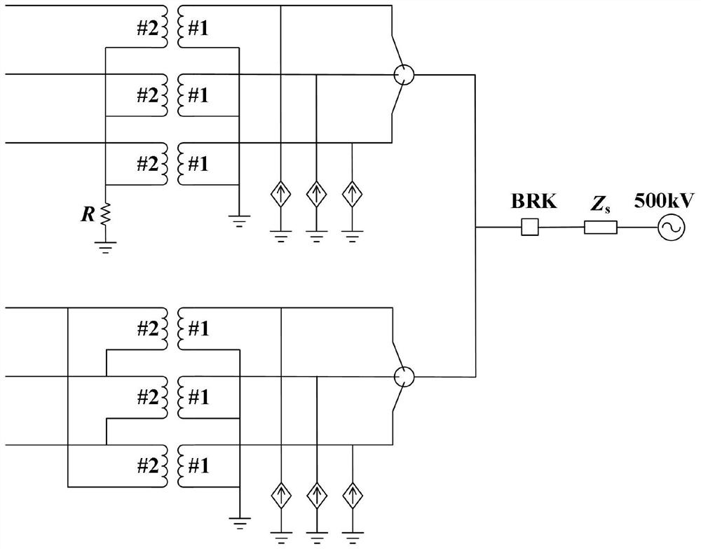
[0032] In this embodiment, as figure 1 As shown, the no-load closing circuit of the converter transformer is composed of Y-bridge and D-bridge converter transformers, and the Y-bridge and D-bridge converter transformers include a single-phase double-winding transformer, a three-phase circuit breaker, and an AC power grid. The primary side of the Y-bridge converter adopts a star connection method, and its neutral point is grounded, and the secondary side also adopts a star connection method, and its neutral point is grounded through an infinite resistance; the primary side of the D-bridge converter adopts a star connection method, in which The neutral point is grounded, and the secondary side adopts the delta connection method. The Y-bridge and D-bridge converters are connected to the 500kV AC system through the same three-phase circuit breaker. The three-phase circuit breaker is connected in series with a 1500Ω closing resistor. After 6ms of switching on, the closing resistor ...


PUM


Abstract

The invention discloses a commutation transformer phase-selective closing excitation inrush current suppression method based on bias magnet simulation. The method includes: 1. Estimating the three-phase residual magnetism values ​​of Y-bridge and D-bridge converter transformers; 2. Extracting and considering the circuit breaker series connection The influence of the gate resistor on the closing bias amplitude and phase is used to construct the bias function; 3. Compare the residual magnet estimated when the converter transformer is opened with the bias function to obtain the appropriate closing time of the converter transformer. . The present invention can utilize the residual magnetism when the converter transformer opens and the bias magnetism when it closes to offset each other, effectively improves the excitation inrush current suppression effect of the converter transformer, and helps to suppress commutation problems during maintenance of high-voltage direct current transmission projects and changes in operating modes. The excitation inrush current caused by the transformer closing and charging can improve the commutation failure problem caused by the excitation inrush current of the commutation transformer.

Description

Technical field [0001] The invention relates to a commutation variable phase closing excitation inrush current suppression method based on bias magnet simulation, and belongs to the technical field of power transformer excitation inrush current suppression. Background technique [0002] UHV DC transmission has the characteristics of large transmission capacity and long distance. It is the main transmission technology for realizing power transmission from large energy bases in southwest and northwest my country. Converter transformer refers to the power transformer that connects the converter bridge and the AC system. It is one of the core equipment of DC transmission. The basic structure of UHV DC transmission converter usually consists of two 6-pulse converter bridges connected in series to form a 12-pulse converter bridge. , at the same time, among the two groups of converter transformers, one group adopts Y-Y connection and the other group adopts Y-Δ connection. The diffe...

Claims


Application Information

Patent Timeline
Patent Type & Authority Patents(China)
IPC IPC(8): H02J3/36H02H9/00
CPCH02J3/36H02H9/002H02J2003/365Y02E60/60
Inventor 陈忠杨为胡迪韩平平童青洋孙浩然
Owner ELECTRIC POWER RES INST OF STATE GRID ANHUI ELECTRIC POWER
Why Eureka
Try Eureka