
Algorithm for realizing 2.5D mounting guided by 2D camera

A camera and algorithm technology, applied in the field of cameras, can solve problems such as inaccurate calibration and susceptibility to interference from various external factors, so as to achieve the effect of fast photographing speed and improved production efficiency

Active Publication Date: 2021-06-15
SHENZHEN VISION DRAGON INTELLIGENT SENSOR CO LTD
View PDF12 Cites 0 Cited by
  • Summary
  • Abstract
  • Description
  • Claims
  • Application Information

AI Technical Summary

Problems solved by technology

The resulting consequence is that the calibration is inaccurate and is easily interfered by various external factors.

Method used


Image

  • Algorithm for realizing 2.5D mounting guided by 2D camera
  • Algorithm for realizing 2.5D mounting guided by 2D camera
  • Algorithm for realizing 2.5D mounting guided by 2D camera

Examples


Embodiment Construction

[0054] In order to make the object, technical solution and advantages of the present invention more clear, the present invention will be further described in detail below in conjunction with the accompanying drawings and embodiments. It should be understood that the specific embodiments described here are only used to explain the present invention, not to limit the present invention.

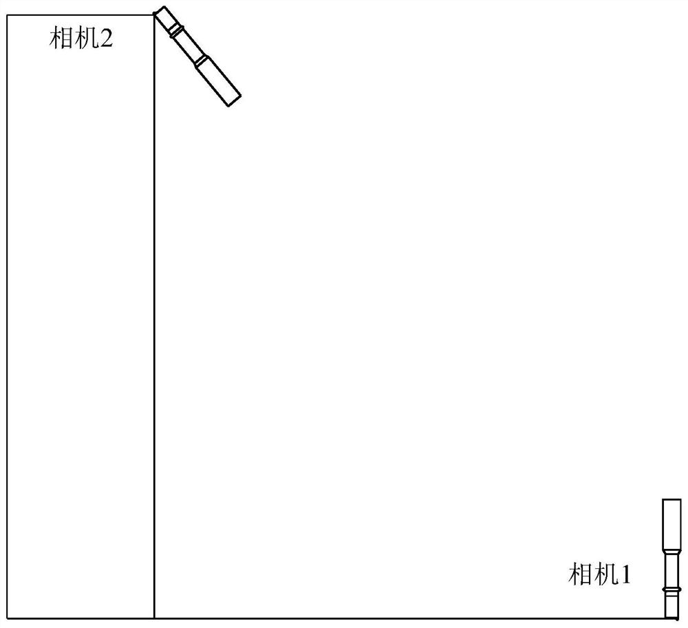
[0055] refer to figure 1 As shown, it is a schematic diagram of camera positions when the present invention is implemented, and camera 1 and camera 2 are two 2D cameras. Camera 1 is installed vertically upward to shoot the fitting object, and camera 2 is installed obliquely and perpendicular to the fitting plane to shoot the fitting target. Such as figure 1 shown.

[0056] Such as figure 2 As shown, this algorithm involves two attitudes of the 6-axis robot. When camera 1 takes a picture, the robot uses pose A. The robot uses posture B during placement.

[0057] World coordinate system: S...


PUM


Abstract

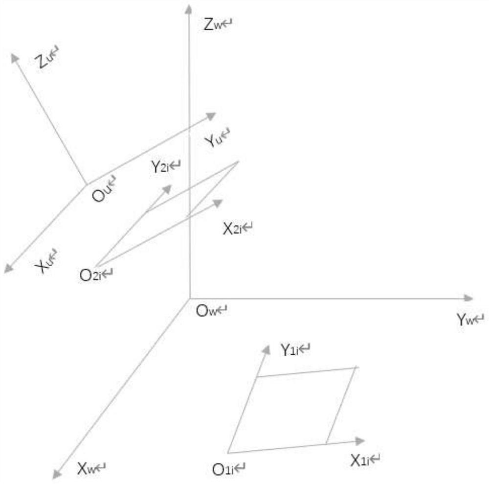
The invention relates to an algorithm for realizing 2.5D mounting guided by a 2D camera, the algorithm uses two cameras, the camera 1 takes a picture of an object, and the camera 2 takes a picture of a target; the algorithm relates to an image coordinate system, an output coordinate system, a world coordinate system and a user coordinate system, and conversion of data among the four coordinate systems, the image coordinate system and the output coordinate system are plane rectangular coordinate systems, and the world coordinate system and the user coordinate system are space rectangular coordinate systems. The algorithm is suitable for the conditions that the fitting object and the fitting target are not in the same plane, and the target fitting plane and the object photographing plane are not changed once determined, 3D mounting can be converted into 2D mounting by using the method, and an expensive 3D camera is replaced by a common 2D industrial camera.

Description

technical field [0001] The invention belongs to the technical field of cameras, and in particular relates to a method for guiding two objects on different planes to be mounted by a 2D camera in a space rectangular coordinate system and for calculating the bonding coordinates. Background technique [0002] In daily life, cameras are widely used, especially when we paste and calibrate objects in different coordinate systems. [0003] Generally speaking, the production cost of the 3D stereoscopic target is relatively high, and the processing accuracy is limited. At present, what people commonly use is camera calibration based on 2D planar targets. [0004] In this calibration method, the camera is required to shoot the same plane target in more than two different directions, and in this case, the camera can move freely without knowing the motion parameters. The resulting consequence is that the calibration is inaccurate and is easily disturbed by various external factors. ...

Claims


Application Information

Patent Timeline
IPC IPC(8): G06T7/80G06T7/70
CPCG06T7/85G06T7/70
Inventor 石冲何伟丁少华
Owner SHENZHEN VISION DRAGON INTELLIGENT SENSOR CO LTD
Learn More