
Pendant and manufacturing process thereof

A manufacturing process and pendant technology, which is applied in the field of accessories, can solve the problems of reducing the quality and durability of pendants, and the frame is easy to deform, so as to improve the quality and durability of use, increase the degree of firmness, and save costs.

Pending Publication Date: 2021-06-15
深圳市冠华珠宝有限公司
View PDF5 Cites 0 Cited by
  • Summary
  • Abstract
  • Description
  • Claims
  • Application Information

AI Technical Summary

Problems solved by technology

[0004] Regarding the related technologies mentioned above, the inventor believes that in order to improve the comfort of wearing, the thickness of the frame will be designed to be relatively thin to reduce the overall weight of the pendant. However, this will lead to easy deformation of the frame and reduce the quality and durability of the pendant.

Method used


Image

  • Pendant and manufacturing process thereof
  • Pendant and manufacturing process thereof
  • Pendant and manufacturing process thereof

Examples


Embodiment 1

[0043] This example discloses a pendant.

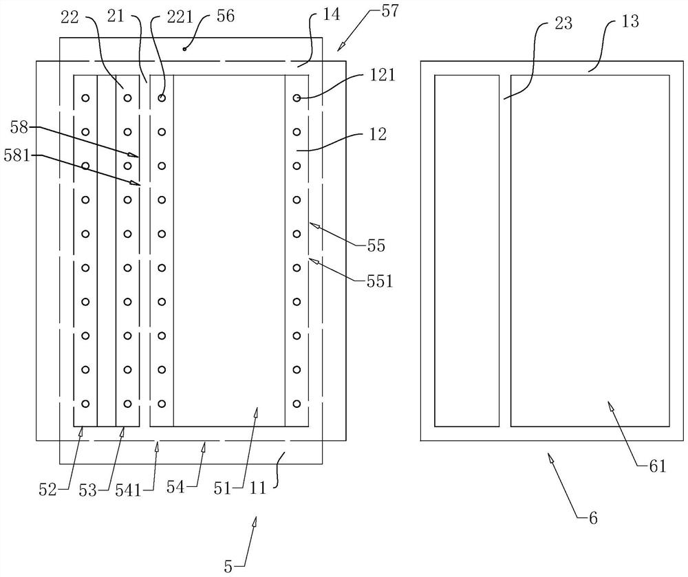
[0044] Such as figure 1 As shown, a pendant includes a frame 1, a support strip 2, a link 3, and a bead block 4. The frame 1 is a rectangular frame structure, and the support strip 2 is a long square structure, and the support strip 2 is connected to the opposite side of the frame 1. The support strip 2 extends in the longitudinal direction of the frame 1, and the link 3 is in a cylinder structure, and the link 3 is perpendicular to the support strip 2, and both ends of the link 3 are respectively connected to the opposite sides of the frame 1. The connecting rod 3 is provided with a plurality of vertical spacers of the length direction of the frame 1, and the bead block 4 is set and slide to be connected to the link 3, and the bead block 4 is provided with a plurality of links 3, so that the pendant In a structure similar to the abacus.

[0045] Such as figure 1 with figure 2 As shown, the frame 1 includes a frame plate 14, the outer plate...

Embodiment 2

[0073] This example discloses a pendant.

[0074] Such as Figure 4 As shown, the pendant of the present embodiment and the pendant of the first embodiment is that the outer plate 11 of the present embodiment is provided with a connection block 8 and an elastic block 9.

[0075] In the present embodiment, the outer plate 11 is divided into two first outer side plates 111 and two second outer side plates 112, and the first outer side plate 111 is adjacent to the second outer side plate 112; the connection block 8 is fixed to the first At both ends of the outer plate 111, the connecting block 8 includes a fixing portion 81 and a cartridge portion 82, and the fixing portion 81 is perpendicular to the cartridge portion 82 and integrally molded, the fixing portion 81 is fixed to the first outer side plate 111, the cartridge portion 82 facing The direction of the adjacent second outer side plate 112 extends, and the pick-up portion 82 is abutted from the second outer side plate 112 from ...


PUM


Abstract

The invention discloses a pendant and a manufacturing process thereof. The pendant comprises a frame, a frame inner cavity is formed in the frame, a plurality of connecting rods are arranged between the two opposite sides of the frame, the side walls of the connecting rods are sleeved with a plurality of bead blocks, a plurality of mounting holes allowing the two ends of the connecting rods to penetrate through are formed in the inner walls of the two opposite sides of the frame, and two ends of the connecting rod extend into the frame inner cavity. The pendant has the effect of improving the use quality and durability of the pendant.

Description

Technical field [0001] The present application relates to the field of jewelry, in particular, involving a pendant and manufacturing processes. Background technique [0002] With the improvement of people's living standards, people are more focused on dressing decoration, so the market of jewelry is constantly expanding; pendants are common jewels, usually through rope or chain wear in the neck, pendant, and different shapes. To adapt to the aesthetic style of different people. [0003] Some pendants will be designed to set a plurality of connectors in the frame, and the links such as bead blocks are served, thereby forming a pendant, and the chain is connected to the frame to wear the pendant to wear a pendant. unit. [0004] In response to the above-described related techniques, the inventors believe that in order to improve the wearing comfort, the thickness of the frame will be more thin to reduce the overall weight of the pendant, but this will cause the edge to easily defor...

Claims


Application Information

Patent Timeline
Patent Type & Authority Applications(China)
IPC IPC(8): A44C25/00A44C27/00
CPCA44C25/001A44C27/00
Inventor 庄文溪陈楚焕
Owner 深圳市冠华珠宝有限公司
Learn More