
Cabbage harvester

A harvester and cabbage technology, applied in the field of harvester, can solve the problems of poor applicability harvesting mechanism, easy to damage cabbage, etc., and achieve the effect of improving efficiency, reducing wear and avoiding skew

Active Publication Date: 2021-06-15
NANJING AGRI MECHANIZATION INST MIN OF AGRI
View PDF13 Cites 1 Cited by
  • Summary
  • Abstract
  • Description
  • Claims
  • Application Information

AI Technical Summary

Problems solved by technology

[0003] The technical problem to be solved by the present invention is that the walking mechanism of the prior art cabbage harvester has poor applicability and the harvesting mechanism is easy to damage the cabbage

Method used


Image

  • Cabbage harvester
  • Cabbage harvester
  • Cabbage harvester

Examples


Embodiment 1

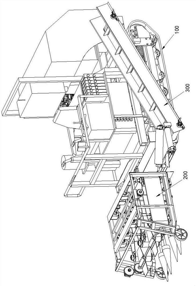
[0031] like figure 1 As shown, the cabbage harvester of this embodiment includes a traveling mechanism 100, a harvesting mechanism 200, a transmission mechanism 300 and a controller;

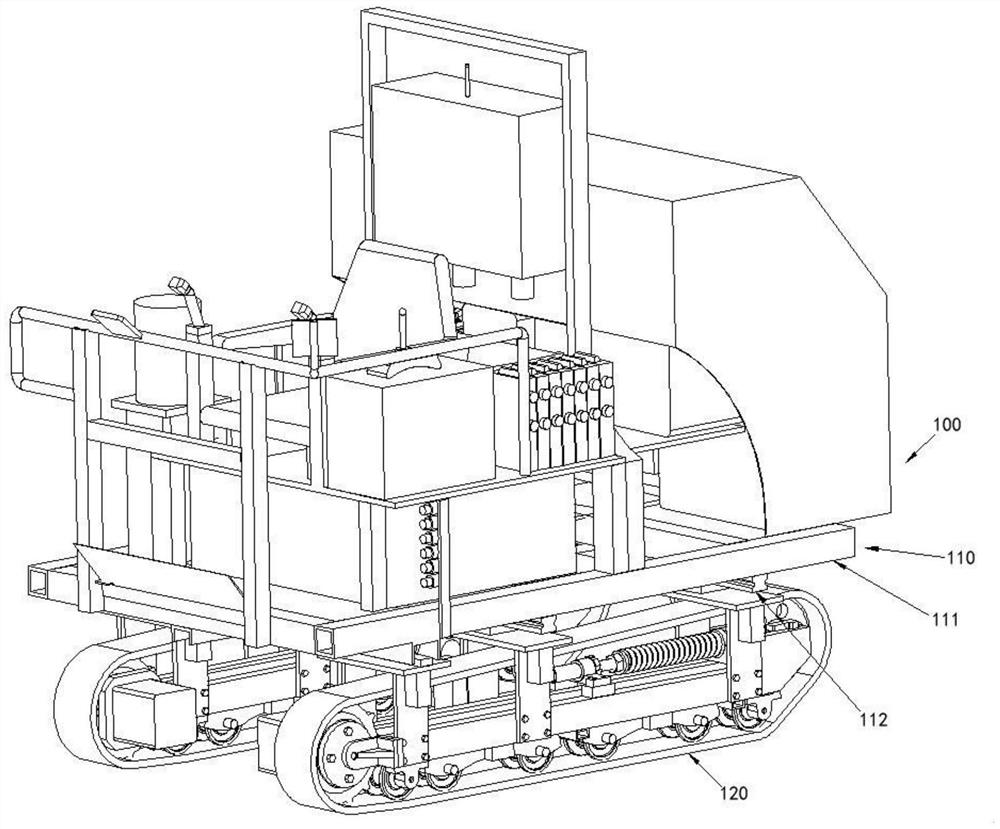
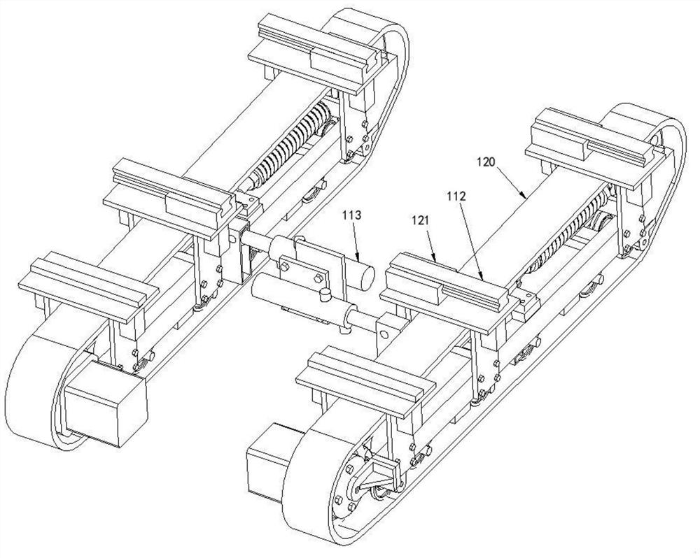
[0032] like figure 2As shown, the traveling mechanism 100 includes a chassis assembly 110, two crawler belt assemblies 120, an internal combustion engine, a first hydraulic pump, a motor and a second hydraulic pump, the chassis assembly 110 includes a chassis frame 111, a slider 112 and a hydraulic cylinder 113, and the chassis frame 111 Used to carry equipment such as cab, internal combustion engine, first hydraulic pump, motor, second hydraulic pump, control system, harvesting mechanism 200 and transmission mechanism 300, slide block 112 and hydraulic cylinder 113 are installed on the bottom of chassis frame 111, such as image 3 As shown, the track assembly 120 is provided with a slide rail 121 perpendicular to the track, the slider 112 is located in the slide rail 121, the number of hydrau...

Embodiment 2

[0042] like Figure 7 As shown, the cabbage harvester of this embodiment is basically the same as that of Embodiment 1, except that the cabbage harvester of this embodiment is provided with an angle sensor 260 and a driving lever 270 on the harvesting platform 210, and the driving lever 270 is rotatable. Installed on the harvesting stand 210, a pair of driving levers 270 is located above a pair of extracting rollers 222, and the angle sensor 260 measures the rotation angle of the driving lever 270 and transmits the measurement result to the controller; when the rotation angle of the pair of driving levers 270 When the difference is greater than the set value, the controller modifies the speeds of the two track assemblies 120 to change the forward direction of the traveling mechanism 100;

[0043] like Figure 7 As shown, before the cabbage 400 enters the extraction roller 222, the two driving levers 270 will be synchronously triggered to rotate. Deviation, this situation is ...


PUM


Abstract

The invention discloses a cabbage harvester. The cabbage harvester comprises a walking mechanism, a harvesting mechanism and a conveying mechanism. The walking mechanism comprises a chassis assembly and two crawler belt assemblies, the chassis assembly comprises a chassis frame, sliding blocks and two hydraulic cylinder, the sliding blocks and the hydraulic cylinders are both installed at the bottom of the chassis frame, sliding rails perpendicular to crawler belts are arranged on the crawler belt assemblies, the sliding blocks are located in the sliding rails, telescopic rods of the two hydraulic cylinders are correspondingly connected with the two crawler belt assemblies, and the hydraulic cylinders are parallel to the sliding rails. The harvesting mechanism and the conveying mechanism are both installed on the walking mechanism, the harvesting mechanism is used for harvesting cabbages, and the conveying mechanism is used for conveying the harvested cabbages. According to the cabbage harvester, the sliding blocks and the sliding rails are arranged between the chassis frame and the crawler belt assemblies, lateral movement of the crawler belt assemblies is achieved through the hydraulic cylinders, and then the distance between the two crawler belt assemblies is changed, so that the crawler belt assemblies adapt to the cabbages of different cultivation agriculture standards.

Description

technical field [0001] The invention relates to the field of agricultural machinery, in particular to a harvester for harvesting cabbage and other bulbous vegetables. Background technique [0002] Cabbage is a vegetable with a sturdy main stem and leaves rolled up to form a leaf ball. It is a common edible vegetable with high nutritional value and is widely grown around the world. At present, the cabbage planted in the fields is arranged in neat rows and can be harvested mechanically using harvesters. The prior art cabbage harvester mainly includes a traveling mechanism and a harvesting mechanism. The traveling mechanism loads the harvesting mechanism and walks straight along the cabbage arrangement direction. The harvesting mechanism is provided with a pulling roller and a cutter head. The roots of the kale are then cut. The main defects of the prior art cabbage harvester are: 1. The distance between the two groups of load wheels or the load crawler of the traveling mecha...

Claims


Application Information

Patent Timeline
IPC IPC(8): A01D45/26A01D67/00A01D69/00A01D57/20
CPCA01D45/26A01D67/00A01D69/00A01D57/20
Inventor 张健飞宋志禹曹光乔金月蒋清海杨光
Owner NANJING AGRI MECHANIZATION INST MIN OF AGRI
Learn More