Implementation method of large-scale planar array multi-beam forming system

A planar array and implementation method technology, applied in the direction of analog/digital conversion calibration/testing, etc., can solve the problems of high price, too many receiving channels, and complex structure of the signal receiving system, so as to reduce the demand for quantity and system complexity and cost reduction effect

Pending Publication Date: 2021-06-11
XI AN JIAOTONG UNIV
View PDF0 Cites 0 Cited by
  • Summary
  • Abstract
  • Description
  • Claims
  • Application Information

AI Technical Summary

Problems solved by technology

[0006] The problem to be solved by the present invention is that the current large-scale antenna array has too many receiving channels, which leads to complex structure and high price of the signal receiving system.

Method used


Image

  • Implementation method of large-scale planar array multi-beam forming system
  • Implementation method of large-scale planar array multi-beam forming system
  • Implementation method of large-scale planar array multi-beam forming system

Examples


Embodiment Construction

[0023] The implementation method of the large-scale planar array multi-beamforming system proposed by the present invention will be described in detail below in conjunction with the accompanying drawings:

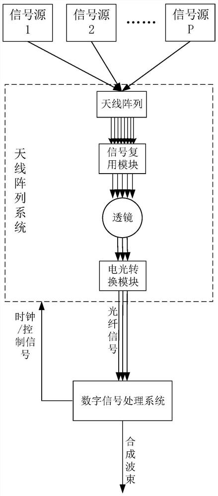
[0024] In the present invention, the signals received by the array are multiplexed and combined in the direction of the azimuth plane (pitch plane), and then enter the lens for analog beamforming in the direction of the pitch plane (azimuth plane), and several beams in desired directions are selected from the numerous beams output by the lens , and transmit it to the remote digital signal processing system for signal demultiplexing and digital beamforming. Since the signal bandwidth after multiplexing is very large, we use optical fiber for signal transmission between the antenna array and the remote digital signal processing system to ensure the transmission bandwidth and transmission rate of the signal. Different from the traditional beamforming system, here we greatly re...


PUM


Abstract

The invention provides an implementation method of a large-scale planar array multi-beam forming system. An antenna array of a signal receiving system is a planar antenna array with M * N array elements. The method comprises the following steps: after an array receives a signal, sending the signal into a low noise amplifier, a frequency mixer and a band-pass filtering module according to an azimuth plane direction to obtain multiple paths of beam signals with different frequencies, and multiplexing and combining the beam signals in the direction; employing a lens for carrying out analog beam forming on the combined multiplexing signals in the pitching plane direction; enabling the signal to pass through an electro-optical conversion module, outputting the signal to a far end through an optical fiber, enabling the signal to be subjected to photoelectric conversion, down-conversion and A / D conversion at the far end, and obtaining a multiplexed digital wave beam; and finally enabling the digital wave beam to be subjected to demultiplexing and digital wave beam forming. According to the invention, the complexity of the system is reduced; meanwhile, the signal is transmitted between the antenna array system and the far-end digital signal processing system by using the optical fiber, so that the transmission bandwidth and the transmission rate are improved.

Description

technical field [0001] The invention belongs to the technical field of array signal processing, in particular to a method for realizing a large-scale planar array multi-beam forming system. Background technique [0002] According to different implementation methods, array beamforming can be divided into analog beamforming and digital beamforming. As the name implies, analog beamforming is to use analog devices (such as mixers, time switches, low noise amplifiers, filters, phase shifters, etc.) The signal is converted into a digital signal after being down-converted, and then processed in the digital domain by a digital signal processing unit. [0003] Specifically, analog beamforming is to first pass the signal received by each array element through a low-noise amplifier, down-conversion, low-pass or band-pass filter to obtain intermediate frequency or baseband array element signals, and then use the data of these signals to pass through The corresponding beamforming algor...

Claims


Application Information

Patent Timeline
IPC IPC(8): H03M1/10
CPCH03M1/10Y02D30/70
Inventor 王文杰张晨皓洪玺王越
Owner XI AN JIAOTONG UNIV
Why Eureka
Try Eureka