
Low-voltage direct-current redundant power supply control system

A power supply control, low-voltage DC technology, applied in the direction of collectors, electric vehicles, electrical components, etc., can solve the problems of secondary winding burning, data interruption, unable to automatically complete the battery and mains conversion, etc., to ensure the stability of power supply , the effect of ensuring safety

Pending Publication Date: 2021-06-11
重庆伟仕达电子有限公司
View PDF0 Cites 2 Cited by
  • Summary
  • Abstract
  • Description
  • Claims
  • Application Information

AI Technical Summary

Problems solved by technology

[0002] In DC power supply, a transformer is generally used to step down and rectify the mains power and provide it to the subsequent load. However, there are unstable states in the power supply process of the mains power, such as overvoltage, power failure, etc. In this case It is necessary to implement overvoltage protection to switch the power supply of the mains. However, after the cut-off, for example, sensors in the Internet of Things need to collect continuous data in real time. Once the power supply is interrupted, it will cause data interruption, which will affect the monitoring and control of the Internet of Things. Existing In technology, batteries and mains power are often used to form redundant power supply. However, the existing battery-based redundant power supply control system often has complex circuit structures, and there is a phenomenon of switching lock, which cannot automatically complete the conversion of batteries and mains power. Although there are Circuits that can be converted, but these circuits often rely on control chips, and their circuit structures are complex
[0003] On the other hand, as a part of the redundant power supply system, the battery often has the risk of reverse connection. The reverse connection of the battery cannot make the whole system work normally, and the high voltage when it is powered on will reversely impact the secondary winding of the transformer. A high self-inductance electromotive force is generated in the secondary winding, which causes the secondary winding to burn out, and even endangers the subsequent circuit, resulting in damage to the entire system.

Method used


Image

  • Low-voltage direct-current redundant power supply control system
  • Low-voltage direct-current redundant power supply control system

Examples


Embodiment Construction

[0027] Below in conjunction with accompanying drawing, the present invention is described in further detail:

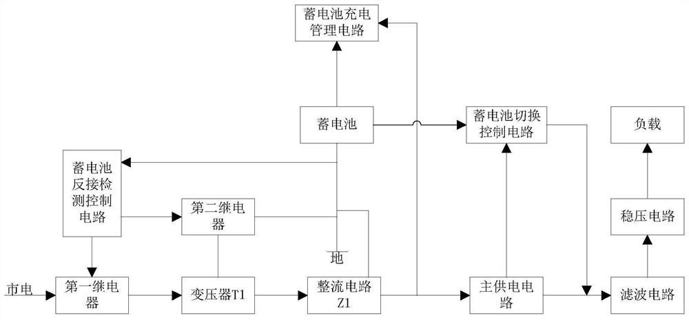
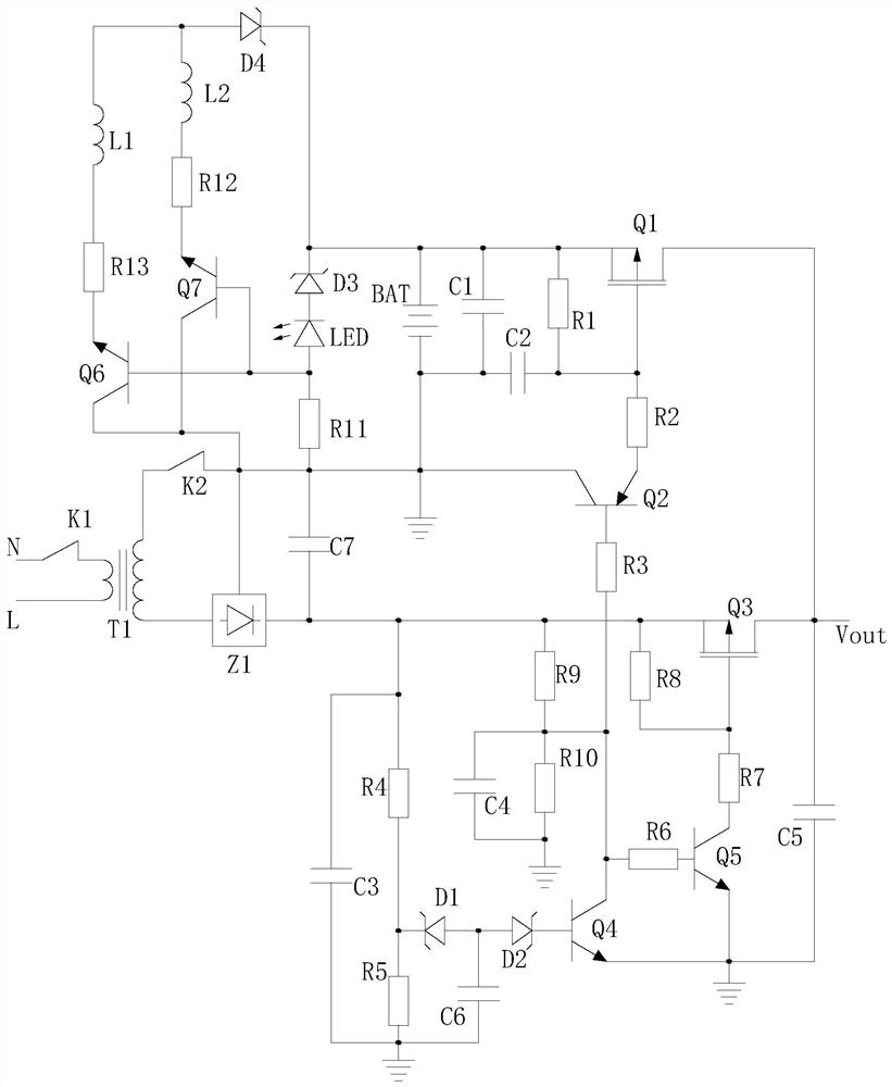
[0028] A low-voltage DC redundant power supply control system provided by the present invention includes a transformer T1, a rectifier circuit Z1, a main power supply circuit, a battery BAT, a battery charging management circuit, a battery switching control circuit, a first relay, a second relay, and battery reverse connection detection control circuit;

[0029] The first relay and the second relay are normally closed relays;

[0030] The normally closed switch K1 of the first relay is set in the energization circuit of the primary winding of the transformer T1, the normally closed switch K2 of the second relay is set between the secondary winding of the transformer T1 and the ground, and the battery reverse connection detection control circuit is used to detect the battery Whether to reverse the connection and control the disconnection of the first relay and the sec...


PUM


Abstract

The invention provides a low-voltage direct-current redundant power supply control system, and the system comprises a transformer T1, a rectifying circuit Z1, a main power supply circuit, a storage battery BAT, a storage battery charging management circuit, a storage battery switching control circuit, a first relay, a second relay and a storage battery reverse connection detection control circuit. A normally-closed switch K1 of the first relay is arranged in a power-on loop of a primary winding of the transformer T1, a normally-closed switch K2 of the second relay is arranged between a secondary winding of the transformer T1 and the ground, and the storage battery reverse connection detection control circuit is used for detecting whether the storage battery is reversely connected or not and controlling the first relay and the second relay to be disconnected; the positive output end of a secondary winding of the transformer T1 is connected with the input end of the rectifying circuit Z1, the output end of the rectifying circuit Z1 is connected with the input end of the main power supply circuit, and the output end of the main power supply circuit supplies power to a load; the input end of the storage battery switching control circuit is connected to the positive electrode of the storage battery BAT, the output end of the storage battery switching control circuit supplies power to a load, and the control input end of the storage battery switching control circuit is connected with the detection output end of the main power supply circuit.

Description

technical field [0001] The invention relates to a power supply control system, in particular to a low-voltage DC redundant power supply control system. Background technique [0002] In DC power supply, a transformer is generally used to step down and rectify the mains power and provide it to the subsequent load. However, there are unstable states in the power supply process of the mains power, such as overvoltage, power failure, etc. In this case It is necessary to implement overvoltage protection to switch the power supply of the mains. However, after the cut-off, for example, sensors in the Internet of Things need to collect continuous data in real time. Once the power supply is interrupted, it will cause data interruption, which will affect the monitoring and control of the Internet of Things. Existing In technology, batteries and mains power are often used to form redundant power supply. However, the existing battery-based redundant power supply control system often has ...

Claims


Application Information

Patent Timeline
Patent Type & Authority Applications(China)
IPC IPC(8): H02J9/06H02J7/00
CPCH02J7/0034H02J9/061
Inventor 宋建平
Owner 重庆伟仕达电子有限公司
Learn More