
Inductive coupling assembly, cavity filter and communication radio frequency device

A cavity filter, inductive coupling technology, applied in the field of communication, can solve the problem of limited clutter suppression ability and so on

Active Publication Date: 2021-06-11
盐城东山通信技术有限公司
View PDF5 Cites 0 Cited by
  • Summary
  • Abstract
  • Description
  • Claims
  • Application Information

AI Technical Summary

Problems solved by technology

[0005] The purpose of the present invention is to provide an inductive coupling component, a cavity filter and a communication radio frequency device, so as to at least solve the problem that the existing cavity filter has limited ability to suppress clutter without adding a resonator

Method used


Image

  • Inductive coupling assembly, cavity filter and communication radio frequency device
  • Inductive coupling assembly, cavity filter and communication radio frequency device
  • Inductive coupling assembly, cavity filter and communication radio frequency device

Examples


Embodiment Construction

[0030] The inductive coupling component, cavity filter and communication radio frequency equipment proposed by the present invention will be further described in detail below with reference to the drawings and specific embodiments. It should be noted that all the drawings are in a very simplified form and use imprecise scales, and are only used to facilitate and clearly assist the purpose of illustrating the embodiments of the present invention. In addition, the structures shown in the drawings are often a part of the actual structures. In particular, each drawing needs to display different emphases, and sometimes uses different scales.

[0031] It should be noted that “first” and “second” in the description and claims of the present invention are used to distinguish similar objects in order to describe the embodiments of the present invention, and are not used to describe a specific order or sequence order, it should be understood that the constructs so used are interchangea...


PUM

PropertyMeasurementUnit
Thicknessaaaaaaaaaa

Abstract

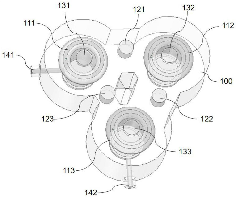
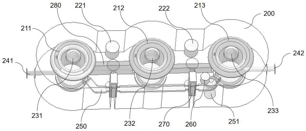
The invention provides an inductive coupling assembly, a cavity filter and a communication radio frequency device. The inductive coupling assembly comprises a cavity, resonators, tuning screw rods and an inductive metal sheet. The cavity is provided with N resonant cavities, and a coupling window is arranged between the i-th resonant cavity and the (i+1)-th resonant cavity; the resonators, the resonant cavities and the tuning screws are arranged in one-to-one correspondence; the inductive metal sheet is connected with the first resonator and the N-th resonator, and the length of the inductive metal sheet is smaller than 1 / 4 wavelength of the resonators. The first resonator and the N-th resonator are connected through the inductive metal sheet, so that an inductive coupling zero point is generated between the first resonator and the N-th resonator; in addition, in the scheme, the arrangement mode of the resonant cavities is not strictly required, the tuning of inductive coupling zero point can be achieved only by adjusting the structure of the inductive metal sheet, and therefore the limitation of the structure and space of the filter is broken through, and the problem that the clutter suppression capability of an existing cavity filter is limited under the condition that the resonators are not added, is solved.

Description

technical field [0001] The invention relates to the technical field of communication, in particular to an inductive coupling component, a cavity filter and communication radio frequency equipment. Background technique [0002] With the rapid development of wireless mobile communication technology, filters, especially cavity coaxial filters, have become an indispensable device in the field of modern communication. [0003] In filter design, in order to achieve low loss, optimize structure and cost, it is necessary to reduce the number of resonators as much as possible, but the suppression effect of the filter on clutter outside the passband will change with the reduction of the number of resonators. Difference. Typically, cross-coupled transmission zeros are added to reduce the number of resonators without compromising the filter's ability to reject spurs. However, in the currently commonly used filters, due to the limitation of topology and cavity space, only limited tra...

Claims


Application Information

Patent Timeline
IPC IPC(8): H01P1/208H01P5/12
CPCH01P1/208H01P5/12
Inventor 梁永团刘建平曹凤杰
Owner 盐城东山通信技术有限公司
Learn More