Eureka AIR delivers breakthrough ideas for toughest innovation challenges, trusted by R&D personnel around the world.

Semiconductor device and manufacturing method thereof

A manufacturing method and semiconductor technology, which is applied in the field of semiconductor devices and semiconductor device manufacturing, and can solve problems such as enlarged feature size, abnormal device short circuit, and insufficient window opening depth in process technology.

Pending Publication Date: 2021-06-11
CHANGXIN MEMORY TECH INC
View PDF0 Cites 0 Cited by
  • Summary
  • Abstract
  • Description
  • Claims
  • Application Information

AI Technical Summary

Problems solved by technology

[0002] When making contact window structures in DRAM, since different contact window structures correspond to different contact hole depths, using the same process to prepare contact holes with different contact window structures will have the problem of insufficient process window opening depth, such as active When the area contact hole has stopped on the surface of the active area, the word line contact hole with a deeper position stays above the word line conductive structure and the window opening has not been completed. If the word line contact hole is continued to be etched, the active area contact hole will be etched to the bottom of the active area. Inside the active area, the sidewall of the contact hole will also have the problem of hole expansion, which will easily cause the feature size of the device to become larger or the device short circuit abnormality caused by sidewall etching

Method used


Image

  • Semiconductor device and manufacturing method thereof
  • Semiconductor device and manufacturing method thereof
  • Semiconductor device and manufacturing method thereof

Examples


Embodiment Construction

[0049] In order to facilitate the understanding of the present invention, the present invention will be described more fully below with reference to the associated drawings. A preferred embodiment of the invention is shown in the drawings. However, the present invention can be embodied in many different forms and is not limited to the embodiments described herein. Rather, these embodiments are provided so that the disclosure of the present invention will be thorough and complete.

[0050] Unless otherwise defined, all technical and scientific terms used herein have the same meaning as commonly understood by one of ordinary skill in the technical field of the invention. The terms used herein in the description of the present invention are for the purpose of describing specific embodiments only, and are not intended to limit the present invention. As used herein, the term "and / or" includes any and all combinations of one or more of the associated listed items.

[0051]It will...


PUM


Abstract

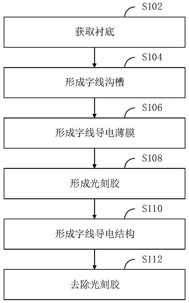
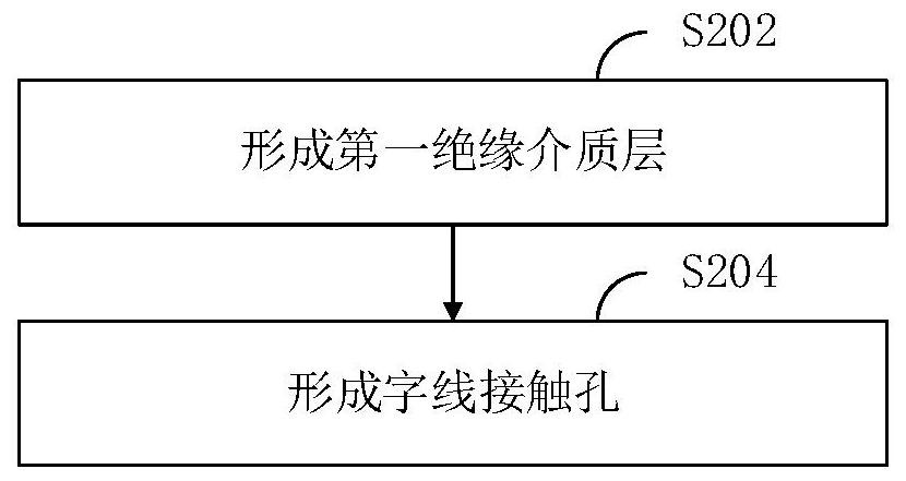
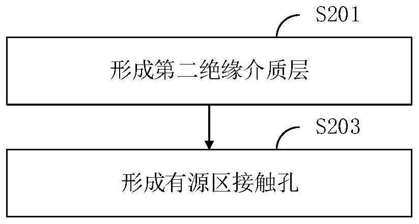
The invention relates to a semiconductor device and a manufacturing method thereof. The method comprises the following steps of acquiring a substrate comprising a memory cell array region, forming a word line groove, forming a word line conductive film in the word line groove, forming photoresist on the surface of the substrate, wherein the photoresist covers the word line conductive film of the word line part and exposes the word line conductive film outside the word line contact part, and enabling the thickness of the word line conductive structure of the word line contact part to be greater than that of the word line conductive structure which is not covered by the photoresist. By forming the photoresist on the surface of the substrate, the thickness of the word line conductive structure of the word line contact part is greater than that of the word line conductive structure which is not covered by the photoresist, so that the depth of the windowing position of the word line contact hole in the word line contact structure is reduced, the process time in the process of forming the contact hole is shortened, the excessive erosion to the side wall of the contact hole with the shallow windowing depth in the contact hole process is reduced, and the short circuit abnormity of the device caused by the abnormity of the contact hole is avoided.

Description

technical field [0001] The invention relates to the technical field of semiconductors, in particular to a semiconductor device and a manufacturing method of the semiconductor device. Background technique [0002] When making contact window structures in DRAM, since different contact window structures correspond to different contact hole depths, using the same process to prepare contact holes with different contact window structures will have the problem of insufficient process window opening depth, such as active When the area contact hole has stopped on the surface of the active area, the word line contact hole with a deeper position stays above the word line conductive structure and the window opening has not been completed. If the word line contact hole is continued to be etched, the active area contact hole will be etched to the bottom of the active area. Inside the active region, the sidewall of the contact hole will also have the problem of hole expansion, which will e...

Claims


Application Information

Patent Timeline
IPC IPC(8): H01L27/108H01L21/8242
CPCH10B12/30H10B12/488
Inventor 吴秉桓
Owner CHANGXIN MEMORY TECH INC
Why Eureka
Eureka Blog
Learn More