Dynamic gas-liquid distribution system and method

A gas-liquid, dynamic technology, used in gas/liquid distribution and storage, pipeline systems, mechanical equipment, etc., can solve the problems of limited gas concentration, difficult to maintain stability, and limited concentration range.

Pending Publication Date: 2021-06-11
重庆渝微电子技术研究院有限公司
View PDF7 Cites 1 Cited by
  • Summary
  • Abstract
  • Description
  • Claims
  • Application Information

AI Technical Summary

Problems solved by technology

[0010] The gas configuration methods required for gas sensor research include static gas distribution and dynamic gas distribution. Static gas distribution is to add a certain amount of known concentration gas into a container of known volume. This method is widely used, especially in commercial and In scientific research; if it is liquid gas distribution, use a micro-syringe to inject a certain volume of liquid into a container of known volume, heat the liquid, and vaporize the liquid; this method is limited by the volume of the container, so that the configured concentration range limited
In addition, the wall of the container has adsorption and chemical reactions on the gas, making it difficult for some active gases to remain stable.
This method is also not conducive to the diffusion of gas, and the concentration of the configured gas is limited. In order to solve the above problems, the dynamic gas distribution method is a good choice

Method used


Image

  • Dynamic gas-liquid distribution system and method

Examples


Embodiment Construction

[0026] The following will clearly and completely describe the technical solutions in the embodiments of the present invention with reference to the accompanying drawings in the embodiments of the present invention. Obviously, the described embodiments are only some, not all, embodiments of the present invention. The following description of at least one exemplary embodiment is merely illustrative in nature and in no way taken as limiting the invention, its application or uses. Based on the embodiments of the present invention, all other embodiments obtained by persons of ordinary skill in the art without creative work fall within the protection scope of the present invention.

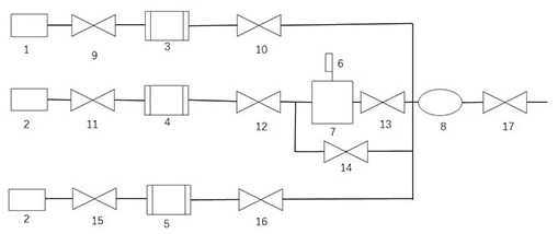
[0027] figure 1 A schematic structural diagram of a dynamic gas-liquid gas distribution system disclosed in the present invention is shown. A dynamic gas-liquid gas distribution system includes a dilution gas (1), a diluted gas (2), a first mass flow controller (3 ), second mass flow controller (4), th...


PUM


Abstract

The invention provides a dynamic gas-liquid distribution system. The dynamic gas-liquid distribution system comprises dilution gas (1), diluted gas (2), a first mass flow controller (3), a second mass flow controller (4), a third mass flow controller (5), a liquid injection pump (6), a liquid evaporator (7), a mixing chamber (8), a plurality of pneumatic valves (9, 10, 11, 12, 13, 14, 15, 16 and 17) and gas transmission pipelines among the components, wherein the liquid evaporator (7) is arranged at an outlet of the liquid injection pump (6); the mixing chamber (8) is used for mixing the dilution gas (1) and the diluted gas (2); and the distribution system is connected to upper computer software through a communication interface, and the upper computer software controls and adjusts the pushing speed of the first mass flow controller (3), the pushing speed of the second mass flow controller (4) and the pushing speed of the liquid injection pump (6) and the evaporation temperature of the liquid evaporator (7). The device has the advantages of simple operation, stable distribution, wide gas concentration and the like.

Description

technical field [0001] The invention relates to the field of gas sensor detection, in particular to a dynamic gas-liquid gas distribution system and method. [0002] technical background [0003] In today's information age, energy, information and materials have constituted the three pillars of the new technological revolution. [0004] Sensors, one of the most effective tools for obtaining information, are developing accordingly. The gas sensor is the gas concentration [0005] A device that converts to a corresponding output signal, usually composed of a sensitive element and a conversion element. gas sensitive [0006] The gas sensor composed of materials is the core part that determines its performance. [0007] The preparation of gas sensors is an exchange involving many disciplines such as chemistry, materials science, physics, and electronic technology. [0008] High-tech fork. It is widely used in industrial production control, family life safety, food industry,...

Claims


Application Information

Patent Timeline
IPC IPC(8): F17D1/00F17D3/01
CPCF17D1/005F17D3/01
Inventor 王琥程马鹏伟
Owner 重庆渝微电子技术研究院有限公司
Why Eureka
Try Eureka