In-cylinder direct injection solenoid valve injector

A technology of in-cylinder direct injection and solenoid valve, which is applied in fuel injection devices, machines/engines, charging systems, etc., and can solve the problem of large average particle size of fuel atomized particles, excessive injection hole diameter and hole depth ratio, and steel ball grinding. Problems such as processing difficulties in flattening, etc., to achieve high product quality, reduce engine fuel consumption, and stable and reliable product performance

Active Publication Date: 2022-05-03
LIUZHOU YUANCHUANG EFI TECH
View PDF0 Cites 0 Cited by
  • Summary
  • Abstract
  • Description
  • Claims
  • Application Information

AI Technical Summary

Problems solved by technology

[0002] Due to the high fuel pressure (11MPa ~ 35MPa) of the existing in-cylinder direct injection solenoid valve injectors, in order to prevent the valve seat from being deformed by pressure, the valve seat sealing structure mostly uses a thick-walled structure, and the injection hole structure is mostly a straight hole or a stepped hole If the ratio of injection hole diameter to hole depth is too large, the average particle size of sprayed fuel atomized particles is relatively large, and it is mixed with air and sucked into the engine to run, resulting in high fuel consumption of the engine.
In addition, the injection medium flows into the valve cavity through the fit gap between the valve seat and the steel ball, and the channel is generally realized by grinding the flat position of the steel ball, or the steel ball is not ground but added through the fit gap between the large valve seat and the steel ball However, it is difficult to grind the flat position of the steel ball. If the steel ball is not ground and the gap between the valve seat and the steel ball is increased, the sealing performance of the injector will be poor.

Method used


Image

  • In-cylinder direct injection solenoid valve injector
  • In-cylinder direct injection solenoid valve injector
  • In-cylinder direct injection solenoid valve injector

Examples


Embodiment 1

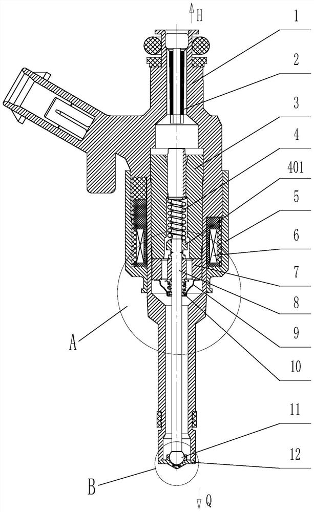
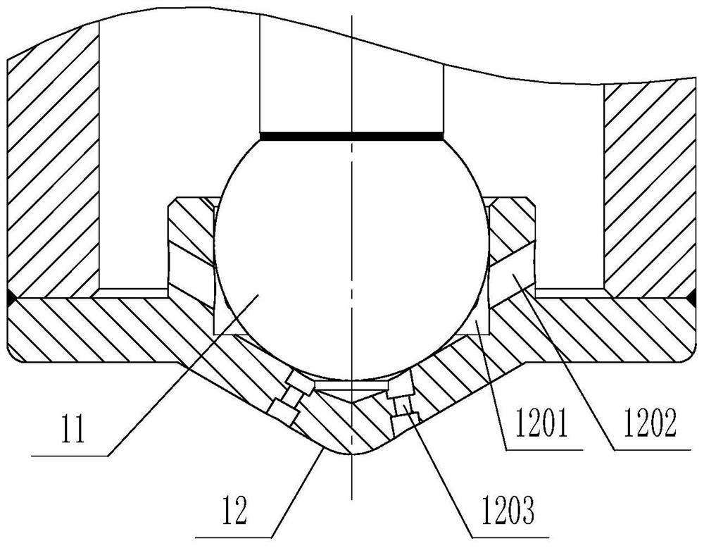
[0034] figure 1 Shown in is an in-cylinder direct-injection electromagnetic valve injector, which includes a casing 1, a filter screen 2, a main shaft 3, a return spring 4, a magnetic sleeve 5, a coil 6, a valve core 7, and a valve core connecting rod 8 , buffer spring sleeve 9, buffer spring 10, steel ball 11, valve seat 12, wherein:

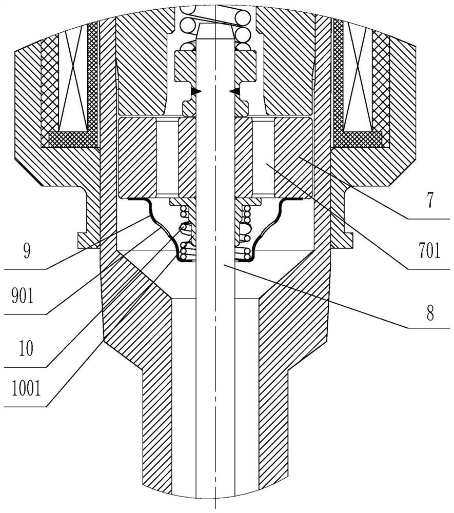
[0035] The filter screen 2 and the main shaft 3 are sequentially installed in the housing 1, the return spring 4 is installed in the main shaft 3, the magnetic sleeve 5 is installed outside the housing 1, and the coil 6 is installed between the magnetic sleeve 5 and the housing 1. coil holder. The middle part of the valve core 7 is connected to the valve core connecting rod 8, and the valve core 7 is provided with a steady flow hole I701 in the axial direction around the valve core connecting rod 8 (see figure 2 ); the rear end of the spool connecting rod 8 is connected to the installation block 401 of the return spring 4 ; the front end of ...


PUM


Abstract

An in-cylinder direct-injection electromagnetic valve type injector, relates to an injector, comprising a housing, a main shaft, a magnetic sleeve, a valve core, a steel ball, and a valve seat, the valve seat has an injection hole and a valve cavity, and the injection hole is composed of The I-shaped injection hole is formed by connecting the large round holes at both ends and the small round hole in the middle; the front end of the valve cavity is a conical valve hole, and the rear end is a circular limit hole. The circular limiting hole is sealed and matched with the steel ball, and a steady flow hole III is provided on the side wall of the circular limiting hole, and the steady flow hole III is connected to the circular limiting hole. The buffer spring sleeve is provided with a steady flow hole II on its side wall; the valve core is provided with a steady flow hole I along its axial direction. The injection hole of the valve seat of the present invention is an I-shaped injection hole, which can effectively reduce the ratio of the injection hole diameter to the hole depth, so that the sprayed atomized particles are smaller, which is beneficial to engine combustion, reduces engine fuel consumption, and makes the product performance stable and reliable. , also has the characteristics of strong versatility, high product quality, good sealing, reasonable and reliable structure, etc., and is easy to popularize and use.

Description

technical field [0001] The invention relates to an injector, in particular to an in-cylinder direct injection electromagnetic valve injector. Background technique [0002] Due to the high fuel pressure (11MPa ~ 35MPa) of the existing in-cylinder direct injection solenoid valve injectors, in order to prevent the valve seat from being deformed by pressure, the valve seat sealing structure mostly uses a thick-walled structure, and the injection hole structure is mostly a straight hole or a stepped hole If the ratio of the injection hole diameter to the hole depth is too large, the average particle size of the sprayed fuel atomized particles is relatively large, and it is mixed with air and sucked into the engine to run, resulting in high fuel consumption of the engine. In addition, the injection medium flows into the valve cavity through the fit gap between the valve seat and the steel ball, and the channel is generally realized by grinding the flat position of the steel ball, ...

Claims


Application Information

Patent Timeline
Patent Type & Authority Patents(China)
IPC IPC(8): F02M51/06F02M61/18
CPCF02M51/061F02M61/188
Inventor 莫韬潘俊运梁国元何汉滔李梁
Owner LIUZHOU YUANCHUANG EFI TECH
Why Eureka
Try Eureka