
Mounting structure and method for container building peripheral guard plate

A technology for installing structures and enclosure boards, applied in building components, building structures, buildings, etc., can solve the problems of troublesome replacement, affecting the use effect, easy to deform, etc. simple effect

Pending Publication Date: 2021-06-11
云南城投众和装饰有限公司
View PDF0 Cites 0 Cited by
  • Summary
  • Abstract
  • Description
  • Claims
  • Application Information

AI Technical Summary

Problems solved by technology

[0003] The installation of the outer protection plate of the existing container building is generally realized in the factory, and the steel plate is directly fixed on the structural frame of the container by welding, which has the following disadvantages: due to the thin steel plate, it is easy to occur during welding or during transportation. Deformation affects the use effect, and it is troublesome to replace later

Method used


Image

  • Mounting structure and method for container building peripheral guard plate
  • Mounting structure and method for container building peripheral guard plate
  • Mounting structure and method for container building peripheral guard plate

Examples


Embodiment 1

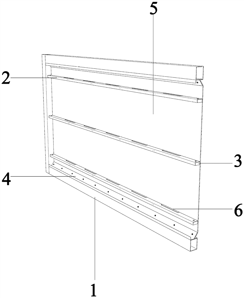
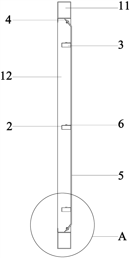
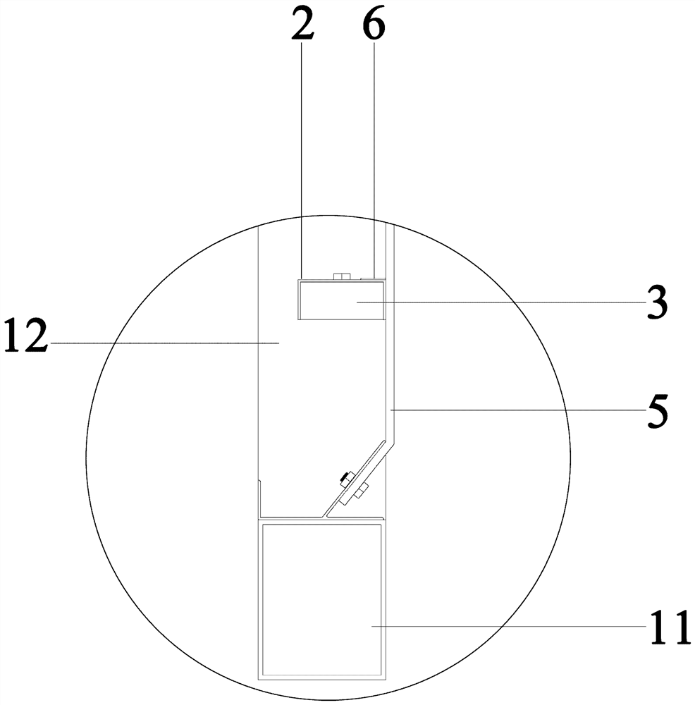
[0039] See Figure 1 to 8 The mounting structure of a container building peripheral strobe provided in the embodiment of the present invention includes a structural frame 1, a structural frame 1 comprising two up and down intervals provided with two vertical frame beams 11 and two vertical welding The frame column 12 on both ends of the frame beam 11 is provided with a plurality of support beams 2, and both ends of the support beam 2 are connected by the L-shaped angle member 3 and the frame column 12 on both sides; the connecting strip 4, which is The "knife" word type metal line, the connection strip 4 symmetrically welded the inner side of the two frame beams 11; the enclosure 5 includes a rectangular envelope body 51, and the two long sides of the enclosure body 51 respectively Extended, the first mounting plate 52 is formed, and a circular first mounting hole 521 arranged in a plurality of specifications is opened on the first mounting plate 52.

[0040] The mounting structure...

Embodiment 2

[0047] See Figure 1 to 8 The mounting structure of a container building peripheral strobe provided by the second embodiment of the present invention is shown, and the present embodiment further makes the following as an improved technical solution based on the above embodiments: support The beam 2 includes a rectangular beam body 21, and the two long side of the beam body 21 is opposed to the first flange 22 and a second flange 23; the first flange 22 is opened with a number of circles for fixing the decorative wall panel. Wire hole; the beam body 21 is opened on a plurality of specifications arranged, and the top of the beam body 21 has a circular first bolt hole 212; the angle member 3 includes a first fixing plate 31, first One end of the fixing plate 31 extends vertically to form a second fixing plate 32, and the first fixing plate 31 is opened with a second bolt hole 311 that matches the first bolt hole 212. Through the arrangement of the above structure, the support beam 2 i...

Embodiment 3

[0049] See Figure 1 to 8The mounting structure of a container building peripheral strobe provided in the first embodiment of the present invention is shown. The present embodiment further has further made the following as an improved technical solution based on the above embodiments: connection The strip 4 includes a connecting plate 41, a constraper 42 that is perpendicular to the connecting plate 41 and a second mounting plate 43 that is obliquely connected to the top of the connecting plate 41; there are several and in the second mounting plate 43; The first mounting hole 521 matches the second mounting hole 431. Through the arrangement of the above structure, the enclosure 5 is connected to the structural frame bolt, which is convenient for on-site construction, and later removable and re-restructure, saving construction costs.


PUM


Abstract

The invention provides a mounting structure for a container building peripheral guard plate. The mounting structure comprises a structural frame, connecting strips and an enclosure plate; the structural frame comprises two frame beams arranged up and down in a spaced mode and two frame columns perpendicularly welded to the two ends of the frame beams; a plurality of supporting beams are arranged between the frame columns; the two ends of each supporting beam are connected with the frame columns on the two sides through L-shaped corner pieces correspondingly; the connecting strips are metal lines shaped like a Chinese character 'Dao (knife)' and symmetrically welded to the inner sides of the two frame beams; the enclosure plate comprises a rectangular enclosure plate body; the two long edges of the enclosure plate body obliquely extend towards the same side to form a first mounting plate; and a plurality of round first mounting holes arranged in a specification mode are formed in the first mounting plate. Compared with the prior art, product industrial production can be achieved, field rapid mounting is achieved, later-period disassembling, assembling, carrying and reassembling can be achieved, and finally the purpose of reducing the comprehensive construction cost is achieved.

Description

Technical field [0001] The present invention relates to the field of container buildings, and specific to the mounting structure and method of container building peripheral guards. Background technique [0002] As my country's scientific and technological development levels continue to increase, container buildings have a great advantage in construction efficiency, economy, removable and sustainable, etc. in terms of construction efficiency, economical, removable and sustainable, and wide application prospects. Container buildings introduced container elements into the assembled building system. It retains the body shape concept of the container, which sets the overall movement and lifting function. After modular production in the factory, it will be transported to the site for assembly and splicing, container construction regardless As a temporary building or a permanent building, it can just satisfy the needs of modern urban construction. [0003] The installation of the existi...

Claims


Application Information

Patent Timeline
Patent Type & Authority Applications(China)
IPC IPC(8): E04H1/12E04B2/74
CPCE04B2/7401E04H1/12E04H2001/1283
Inventor 谢伦杰戴江文
Owner 云南城投众和装饰有限公司
Learn More