Belt breakage prevention chain belt breakage grabbing conveyor for implementing belt breakage prevention chain belt breakage grabbing method

A broken belt and chain belt technology, applied in the direction of conveyors, conveyor objects, transportation and packaging, etc., can solve the problems of large space occupation, difficult installation, large space occupied by belt conveyor overlaps, etc.

Pending Publication Date: 2021-06-11
刘素华
View PDF27 Cites 0 Cited by
  • Summary
  • Abstract
  • Description
  • Claims
  • Application Information

AI Technical Summary

Problems solved by technology

[0002] The currently used belt conveyor uses the sliding friction between the roller and the conveyor belt to transport materials. Due to the excessive tension of the conveyor belt due to the sliding friction, the conveyor belt is easy to expand and contract, easy to deviate, and easy to slip. Since the conveyor belt is driven by sliding friction, the middle part cannot be accelerated. The driving force is installed to assist the transportation, so a powerful motor is installed at the end of the belt conveyor to drive the belt for long-distance heavy-duty transportation. In order to meet the needs of long-distance heavy-duty transportation and to strengthen the tensile strength of the belt, the belt is made very thick. Because the transport belt is too thick, the transport belt is too heavy, difficult to install and transport, and has poor bending performance. Due to the poor bending performance, it is necessary to use super large diameter rollers, resulting in large space occupation, difficult installation, waste of materials, etc. The old belt conveyor is for Reduce the diameter of the drum and the thickness of the transport belt, and make multiple overlapping belt conveyors for lap transportation, resulting in the need to install multiple belt conveyors on the site, making the installation complicated, taking up a lot of space at the lap of the belt conveyor, and requiring a large amount of maintenance. It is labor-intensive and time-consuming and increases the production cost. During the transportation process, in order to prevent the belt of the belt conveyor from slipping and deviation, the belt is pulled very tightly. Because the belt is forcefully straightened, the damage to the belt is increased, and the straightened Even if the belt is pushed by a strong power side, it can only turn less than 15°. Even if it can run in a turn, because the belt is forced to turn by a strong side thrust after being pulled straight, the belt with a huge tension often pushes out of the side push groove. The material on the belt is slid out in a large amount, and the belt is pushed by a strong lateral force, and then pulled by a strong linear force of the drive roller, causing the belt to be seriously deformed and damaged within a very short period of time. The driving force is pulled, and the conveyor belt is often broken or the motor is overloaded and damaged. When the conveyor belt is broken, the conveyor belt is suddenly violently shaken due to the strong pulling force, which often causes major failures such as facility damage, casualties, and long-term shutdown. , heavy losses, costing a lot of manpower and material resources to repair and clean up the site, in order to prevent smashing, there is an armored conveyor belt, which is mainly composed of steel piercing strips piercing the nail plate, because the nail plate needs to rotate around the drum, there is a Gap, leaking material is seriously accumulated, the material will hold up the armored conveyor belt, and the hardened material will lock the armored conveyor belt and cause it to fail to operate. In order to prevent material leakage between the nails, add a belt inside the armored conveyor belt to prevent leakage. The material of the belt and the armored conveyor belt is different, and its rotation radius is different. During the operation, the armored conveyor belt often slips on the upper part of the belt and cannot work normally. The conveyor belt with steel strips is driven by the drive chain to transport materials, so that the conveyor belt does not deviate, slip, and stretch. The transportation of materials is safe and reliable. The strips are rigid, and the middle part of the conveyor belt cannot be transported in troughs. Since the steel strip conveyor belt has no turning operation structure, when turning transportation is required, materials cannot be turned and transported according to site requirements. A transport plane is transported by overlapping the nose and tail at the turning point. Due to the height space required for the overlap of the nose and tail, the equipment is increased. In order to solve the above problems, through decades of research and development, manufacturing and re-study, this invention proposes an anti-break belt grab Chain belt breakage prevention belt catch chain belt breakage belt conveyor

Method used


Image

  • Belt breakage prevention chain belt breakage grabbing conveyor for implementing belt breakage prevention chain belt breakage grabbing method
  • Belt breakage prevention chain belt breakage grabbing conveyor for implementing belt breakage prevention chain belt breakage grabbing method
  • Belt breakage prevention chain belt breakage grabbing conveyor for implementing belt breakage prevention chain belt breakage grabbing method

Examples


Embodiment 1

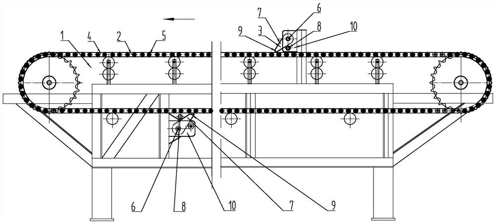
[0180] Such as figure 1 As shown, the anti-breakage belt grab chain belt broken belt conveyor 1 includes a transport chain belt 2 and a chain belt breaker 3, and the transport chain belt 2 includes a conveyor belt 4 and a conveyor belt chain 5, and the conveyor belt chain 5 is arranged on the conveyor belt 4 On both sides, the chain belt breaker 3 includes a belt breaker shaft 6 and a belt breaker 7, the belt breaker 7 is movably buckled with the belt breaker shaft 6, and the belt breaker 7 includes a belt stopper The tooth reversing part 8 and the belt breaker tooth 9 are blocked and the belt tooth reversing part 8 is prevented from catching the belt breaker tooth 9 from reverse rotation. The device bracket 10, the chain belt breaking device 3 is arranged on the chain belt breaking device support 10, when the belt breaking device 7 is movably buckled with the belt breaking device shaft 6 and the belt tooth reversing part 8 is used to stop When grabbing the belt device tooth ...

Embodiment 2

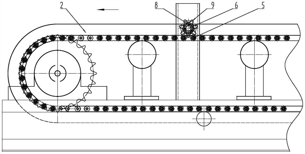
[0188] Such as figure 2 As shown, when using the grabber tooth 9 to mesh with the conveyor belt chain 5, the catcher tooth reversing member 8 is set between the grabber shaft 6 and the grabber tooth 9, and the conveyor chain belt 2. When transporting materials in the forward direction, the conveyor belt chain 5 drives the belt catcher teeth 9 to rotate around the belt breaker shaft 6, so that the conveyor chain belt 2 runs smoothly in the forward direction. Tooth reversing part 8 prevents from catching and breaking belt device tooth 9 and moves reversely around catching and breaking belt device shaft 6, and grabs and breaks belt device tooth 9 and prevents conveyor belt chain 5 from running in reverse.

[0189] Others are with embodiment 1.

Embodiment 3

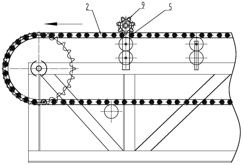
[0191] Such as image 3 As shown, when using the catcher tooth 9 to mesh with the conveyor belt chain 5, the catcher tooth 9 rotates around the grabber shaft 6, and when the conveyor chain belt 2 is forwardly running and feeding, the grabber Teeth 9 buckle the conveyor belt chain 5 and rotate, and when the conveyor chain belt 2 breaks, the belt device teeth 9 are caught to stop the conveyor belt chain 5 from coming off and swinging.

[0192] Others are with embodiment 1.


PUM


Abstract

The invention belongs to the field of machinery and particularly relates to a belt breakage prevention chain belt breakage grabbing conveyor for implementing a belt breakage prevention chain belt breakage grabbing method. According to the belt breakage prevention chain belt breakage grabbing conveyor for implementing the belt breakage prevention chain belt breakage grabbing method, a conveying chain belt breakage grabbing device comprises a conveying chain belt and a chain belt breakage grabbing device, wherein the conveying chain belt comprises a conveying belt and a conveying belt chain, the conveying belt chain is arranged on one side or two sides of the conveying belt, the chain belt breakage grabbing device comprises belt breakage grabbing device shafts and belt breakage grabbing device pieces, the belt breakage grabbing device pieces and the belt breakage grabbing device shafts are movably connected in a buckled manner or are arranged into a whole, the belt breakage grabbing device pieces comprise belt breakage grabbing tooth reverse rotation preventing pieces and belt breakage grabbing device teeth, the conveying chain belt conveys materials in the forward direction, the belt breakage grabbing device teeth are made to rotate around the belt breakage grabbing device shafts, the conveying belt chain is made to run smoothly and forwards at the belt breakage grabbing device teeth, when the conveying chain belt is broken, the belt breakage grabbing tooth reverse rotation preventing pieces prevent the belt breakage grabbing device teeth from reversely moving around the belt breakage grabbing device shafts, and the belt breakage grabbing device teeth prevent the conveying belt chain from reversely running.

Description

technical field [0001] The invention belongs to the field of machinery, and in particular relates to an anti-breakage conveyor for catching broken chains and belts, which implements a method for catching broken belts with broken chains. Background technique [0002] The currently used belt conveyor uses the sliding friction between the roller and the conveyor belt to transport materials. Due to the excessive tension of the conveyor belt due to the sliding friction, the conveyor belt is easy to expand and contract, easy to deviate, and easy to slip. Since the conveyor belt is driven by sliding friction, the middle part cannot be accelerated. The driving force is installed to assist the transportation, so a powerful motor is installed at the end of the belt conveyor to drive the belt for long-distance heavy-duty transportation. In order to meet the needs of long-distance heavy-duty transportation and to strengthen the tensile strength of the belt, the belt is made very thick. ...

Claims


Application Information

Patent Timeline
Patent Type & Authority Applications(China)
IPC IPC(8): B65G43/06B65G23/44B65G45/12
CPCB65G43/06B65G23/44B65G45/12
Inventor 刘素华
Owner 刘素华
Why Eureka
Try Eureka