Vacuum packaging machine

A vacuum packaging machine and packaging machine technology, applied in the direction of packaging under vacuum/special atmosphere, etc., can solve the problems of unfavorable production and use of vacuum packaging machines, increased production costs of vacuum packaging machines, and inability to accommodate vacuum packaging bags, etc., to achieve The effect of reducing material cost and process cost, various choices, and reducing atmospheric pressure

Pending Publication Date: 2021-06-11
GUANGZHOU ARGION ELECTRIC APPLIANCE CO LTD
View PDF0 Cites 1 Cited by
  • Summary
  • Abstract
  • Description
  • Claims
  • Application Information

AI Technical Summary

Problems solved by technology

[0002] Vacuum packaging machines are often used for sealed packaging of articles. The existing cavity-type vacuum packaging machines are made of metal materials in consideration of pressure requirements. The processing technology is complicated and the production cost is high. At the same time, if figure 1 As shown, the vacuum packaging machine in the prior art is limited by the processing technology, the shape of the vacuum chamber 100 is relatively square, and the multiple edge corners of the vacuum chamber 100 cannot play the role of accommodating the vacuum packaging bag, which virtually increases the vacuum chamber. The volume of the vacuum chamber is too large, which puts forward greater requirements on the power of the vacuum pump group, and the high-power vacuum pump group further leads to an increase in the production cost of the vacuum packaging machine, which is not conducive to the production and use of the vacuum packaging machine.

Method used


Image

  • Vacuum packaging machine
  • Vacuum packaging machine
  • Vacuum packaging machine

Examples


Embodiment Construction

[0023] The specific implementation manners of the present invention will be further described in detail below in conjunction with the accompanying drawings and embodiments. The following examples are used to illustrate the present invention, but are not intended to limit the scope of the present invention.

[0024] It should be understood that the terms "front", "rear" and the like are used in the present invention to describe various information, but the information should not be limited to these terms, and these terms are only used to distinguish the same type of information from each other. For example, "before" information could also be called "after" information, and "after" information could also be called "before" information without departing from the scope of the present invention.

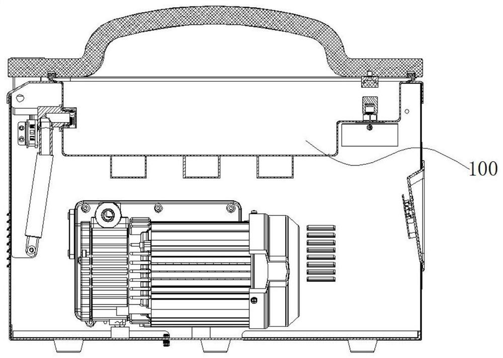
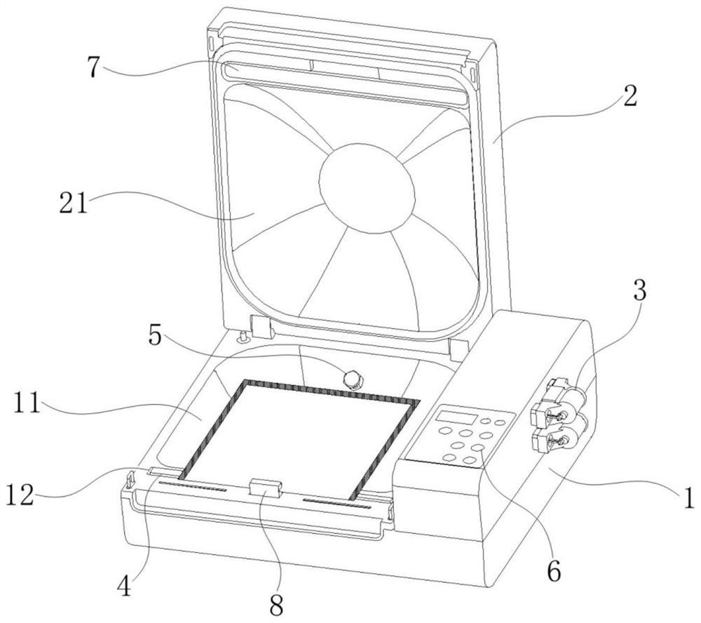
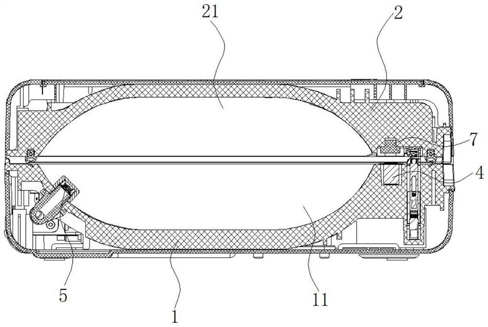
[0025] Such as figure 2 and image 3 As shown, the present invention provides a vacuum packaging machine, which includes a packaging machine body and a vacuum pump group 3, a heater 4,...


PUM


Abstract

The invention relates to the technical field of vacuum packaging, and discloses a vacuum packaging machine. The vacuum packaging machine comprises a base and a top cover which are connected in a hinged mode, wherein a lower cavity is formed in the top face of the base, an upper cavity is formed in the bottom face of the top cover, a heater, a vacuum pump set and a control system are arranged on the base, the vacuum pump set communicates with the lower cavity through an extraction opening formed in the cavity wall of the lower cavity, and the control system is used for controlling the heater and the vacuum pump set to complete heat sealing and suction operation. According to the vacuum packaging machine, stress conditions of the cavity wall of the upper cavity and the cavity wall of the lower cavity of the vacuum packaging machine are improved, the material consumption and the manufacturing process of the cavity walls of the upper cavity and the lower cavity of the vacuum packaging machine are optimized, the material consumption cost and the process cost are reduced, meanwhile, the volume of the vacuum cavity is reduced, the selection cost of the vacuum pump set is reduced, and the manufacturing cost of the vacuum packaging machine is effectively reduced.

Description

technical field [0001] The invention relates to the technical field of vacuum packaging, in particular to a vacuum packaging machine. Background technique [0002] Vacuum packaging machines are often used for sealed packaging of articles. The existing cavity-type vacuum packaging machines are made of metal materials in consideration of pressure requirements. The processing technology is complicated and the production cost is high. At the same time, if figure 1 As shown, the shape of the vacuum chamber 100 in the prior art is limited by the processing technology, and the shape of the vacuum chamber 100 is relatively square. The multiple edge corners of the vacuum chamber 100 cannot play the role of accommodating the vacuum packaging bag, and the vacuum chamber is virtually enlarged. The volume, too large vacuum chamber puts forward greater requirements on the power of the vacuum pump group, and the high-power vacuum pump group further leads to an increase in the production co...

Claims


Application Information

Patent Timeline
IPC IPC(8): B65B31/02
CPCB65B31/02
Inventor 梁国强李灼湖
Owner GUANGZHOU ARGION ELECTRIC APPLIANCE CO LTD
Why Eureka
Try Eureka