Laser welding equipment

A technology of laser welding and equipment, which is applied in the direction of laser welding equipment, welding equipment, welding equipment, etc., can solve the problems of inapplicable mass production operations and low processing efficiency, so as to reduce unqualified products, improve work efficiency, and improve The effect of flatness

Pending Publication Date: 2021-06-11
东莞市合力激光设备有限公司
View PDF0 Cites 4 Cited by
  • Summary
  • Abstract
  • Description
  • Claims
  • Application Information

AI Technical Summary

Problems solved by technology

At present, due to the needs of use, some metal plate products need to be stacked together before welding. The existing metal plates are stacked manually and then placed under the laser welding machine for welding, and then the metal plates are manually moved for other purposes. The welding of parts, the processing efficiency is low, and it is not suitable for mass production operations

Method used


Image

  • Laser welding equipment
  • Laser welding equipment
  • Laser welding equipment

Examples


specific Embodiment 1

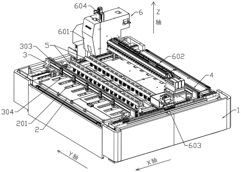
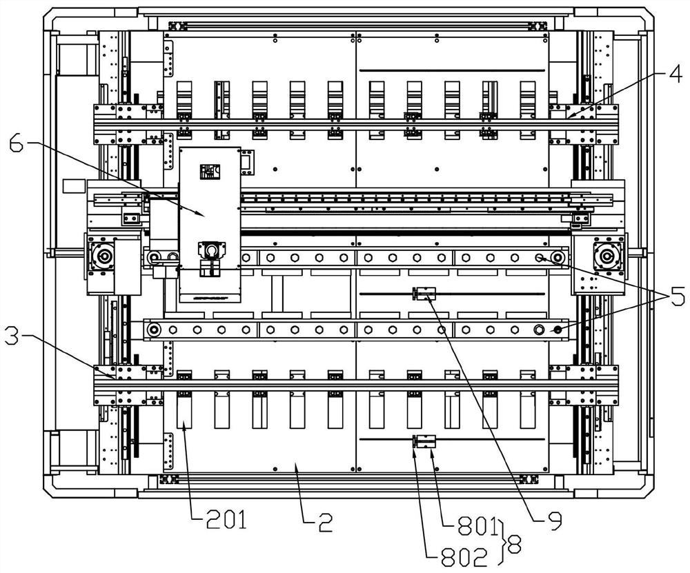
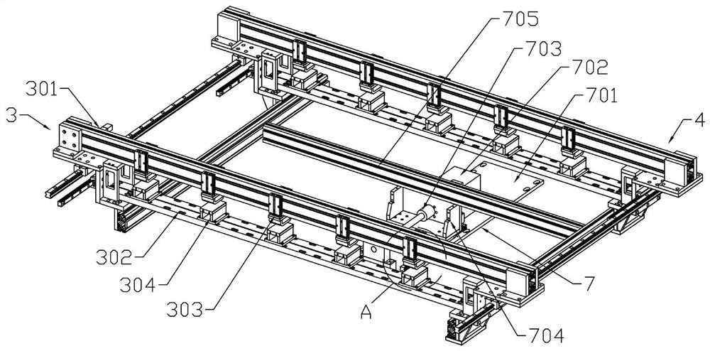
[0025] Specific Example 1: See Figure 1 to Figure 6 , in an embodiment of the present invention, a laser welding device includes a frame 1, a workbench 2 is arranged above the frame 1, and a first conveying device 3, Two sets of pressing device 5, laser welding device 6 and second conveying device 4 with the same structure, the metal plate to be processed is placed on the workbench 2, and the pressing device 5 is movably connected up and down on the workbench 2 to process the metal plate. Pressing and fixing, the laser welding device 6 slides along the X-axis direction on the workbench 2, the laser welding device 6 is above the pressing device 5, and the main driving device 7 is installed below the workbench 2. The first conveying device 3 and the second conveying device 4 are driven by the main driving device 7 to slide synchronously on the worktable 2 along the X-axis direction, and the first conveying device 3 and the second conveying device 4 press the metal plate delive...

specific Embodiment 2

[0036] Specific embodiment 2: refer to Figure 7 and Figure 8 , on the basis of Embodiment 1, the second conveying device 4 includes a third support rod 401 and a suction assembly 402 arranged on the third support rod 401, and the third support rod 401 is slidably connected with the frame 1 , the third support rod 401 is fixedly connected to the connecting frame 705 on the main driving device 7, the suction assembly 402 is above the workbench 2, and the suction assembly 402 includes a vacuum suction cup 402-2 and a suction cylinder 402 -1, the material suction cylinder 402-1 is fixed on the third support rod 401, the material suction cylinder 402-1 is provided with two symmetrically installed on the left and right sides of the third support rod 401, the material suction cylinder The drive shaft of 402-1 is driven and connected with the vacuum chuck 402-2. The vacuum chuck 402-2 is provided with several suction nozzles 402-2-1 connected to the vacuum pump. After the welding i...


PUM


Abstract

The invention provides laser welding equipment. The equipment comprises a rack; a workbench is arranged above the rack; a first conveying device, a laser welding device and a second conveying device are sequentially arranged along the workbench from left to right; the laser welding device slides on the workbench; a main driving device is installed below the workbench; the first conveying device and the second conveying device are driven by the main driving device to synchronously slide on the workbench in the X-axis direction. Compared with the prior art, the laser welding equipment is compact and reasonable in structural design, laser welding machining is conducted through automatic feeding, metal plates are pressed and pulled to the laser welding position through synchronous movement of the first conveying device and the second conveying device to be subjected to laminated welding machining, manual material pulling and conveying are reduced, and the working efficiency of double-layer superposition welding of the metal plates is improved.

Description

technical field [0001] The invention relates to the technical field of automation equipment, in particular to a laser welding equipment. Background technique [0002] Laser welding is an efficient and precise welding method that uses a high-energy-density laser beam as a heat source. It is one of the important aspects of the application of laser material processing technology. At present, due to the needs of use, some metal plate products need to be stacked together before welding. The existing metal plates are stacked manually and then placed under the laser welding machine for welding, and then the metal plates are manually moved for other purposes. The welding of parts has low processing efficiency and is not suitable for mass production operations. Contents of the invention [0003] The object of the present invention is to provide a laser welding device to solve the technical problems in the background art. [0004] In order to achieve the aforementioned object, the...

Claims


Application Information

Patent Timeline
Patent Type & Authority Applications(China)
IPC IPC(8): B23K26/21B23K26/08B23K26/70B23K37/04
CPCB23K26/0876B23K37/0435B23K26/21B23K26/702
Inventor 杨立龙李芸芸
Owner 东莞市合力激光设备有限公司
Why Eureka
Try Eureka