Cutting device for mold production

A cutting device and mold technology, applied in shearing devices, feeding devices, accessories of shearing machines, etc., can solve the problems of reduced work efficiency, damage of mold raw materials, movement of mold raw materials, etc., and achieves high action continuity, The effect of reducing workload and ensuring stability

Inactive Publication Date: 2021-06-11
唐中友
View PDF0 Cites 0 Cited by
  • Summary
  • Abstract
  • Description
  • Claims
  • Application Information

AI Technical Summary

Problems solved by technology

[0002] In the mold production process, a cutting device is needed to facilitate the workers to process the mold raw materials. Some cutting devices have poor clamping effect. When the cutting device processes the mold raw materials, the mold raw materials are prone to move. , resulting in damage to the mold raw material parts, increasing the defective products of the mold raw material parts
[0003] At present, the existing cutting device can effectively clamp the raw material of the mold to ensure the stability when it is cut and reduce the defective rate of the raw material of the mold. However, the cutting device in the prior art clamps the raw material of the mold. Tightening is achieved by using two or more driving equipment, which requires distributed control of the driving equipment, which reduces the efficiency of clamping mold raw materials, thereby reducing work efficiency; at the same time, using two or more The driving equipment achieves clamping, which increases the production cost of the cutting equipment

Method used


Image

  • Cutting device for mold production
  • Cutting device for mold production
  • Cutting device for mold production

Examples


Embodiment Construction

[0022] The following will clearly and completely describe the technical solutions in the embodiments of the present invention with reference to the accompanying drawings in the embodiments of the present invention. Obviously, the described embodiments are only some, not all, embodiments of the present invention.

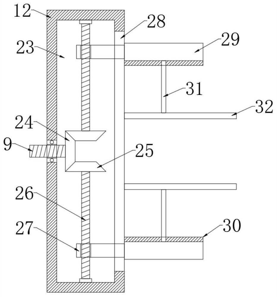
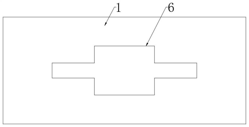
[0023] refer to Figure 1-4 , a cutting device for mold production, comprising a base 1, four support rods 2 are fixedly connected to the base 1, a top plate 3 is fixedly connected to the upper ends of the four support rods 2, and an electric push rod 4 is fixedly connected to the bottom of the top plate 3 , the output end of the electric push rod 4 is fixedly connected with a cutting machine 5, the outer wall of the output end of the electric push rod 4 is fixedly connected with a cross bar 14, and the bottom of the cross bar 14 is provided with two T-shaped slots 15, two T-shaped slots 15 T-blocks 16 are slidably connected inside; wherein, the opposite ends of the ...


PUM


Abstract

The invention discloses a cutting device for mold production. The cutting device comprises a base, four supporting rods are fixedly connected to the base, the upper ends of the four supporting rods are jointly and fixedly connected with a top plate, the bottom of the top plate is fixedly connected with an electric push rod, and the output end of the electric push rod is fixedly connected with a cutting machine. A cross rod is fixedly connected to the outer wall of the output end of the electric push rod, two T-shaped grooves are formed at the bottom of the cross rod, T-shaped blocks are slidably connected to the interiors of the two T-shaped grooves, two supporting blocks are fixedly connected to the base, and threaded cylinders are fixedly connected to the opposite faces of the two supporting blocks. The cutting machine can move through one electric push rod so as to cut a mold raw material part, meanwhile, the mold raw material part can be clamped in multiple directions, the stability of the mold raw material part during cutting is guaranteed, meanwhile, chippings on the mold raw material part can be cleaned, and the labor amount of workers is reduced.

Description

technical field [0001] The invention relates to the technical field of mold processing, in particular to a cutting device for mold production. Background technique [0002] In the mold production process, a cutting device is needed to facilitate the workers to process the mold raw materials. Some cutting devices have poor clamping effect. When the cutting device processes the mold raw materials, the mold raw materials are prone to move. , causing damage to the mold raw material parts, increasing the defective products of the mold raw material parts. [0003] At present, the existing cutting device can effectively clamp the raw material of the mold to ensure the stability when it is cut and reduce the defective rate of the raw material of the mold. However, the cutting device in the prior art clamps the raw material of the mold. Tightening is achieved by using two or more driving equipment, which requires distributed control of the driving equipment, which reduces the effici...

Claims


Application Information

Patent Timeline
Patent Type & Authority Applications(China)
IPC IPC(8): B23D19/00B23D33/02B23Q5/28B23Q11/00
CPCB23D19/00B23D33/02B23Q5/28B23Q11/0042
Inventor 唐中友
Owner 唐中友
Why Eureka
Try Eureka