Eureka AIR delivers breakthrough ideas for toughest innovation challenges, trusted by R&D personnel around the world.

Numerical control tray stamping equipment

A technology of stamping equipment and trays, which is applied in the field of CNC tray stamping equipment, can solve the problems of inconvenient assembly and disassembly, inconvenient adjustment and adjustment of stamping parts, and inconvenient automation of device parts shifting, etc., to achieve improved installation Fixed convenience, convenient transportation and assembly, simple and efficient stamping method

Pending Publication Date: 2021-06-11
傅代伟
View PDF0 Cites 0 Cited by
  • Summary
  • Abstract
  • Description
  • Claims
  • Application Information

AI Technical Summary

Problems solved by technology

[0006] The object of the present invention is to provide a kind of numerical control tower stamping equipment, to solve the similar products proposed in the above background technology, it is inconvenient for users to assemble and disassemble the components of the part stamping equipment, and it is inconvenient for users to further increase the degree of automation of the displacement of device components. Lifting, inconvenient for users to adjust and set the height position of stamping parts adaptively

Method used


Image

  • Numerical control tray stamping equipment
  • Numerical control tray stamping equipment
  • Numerical control tray stamping equipment

Examples


Embodiment Construction

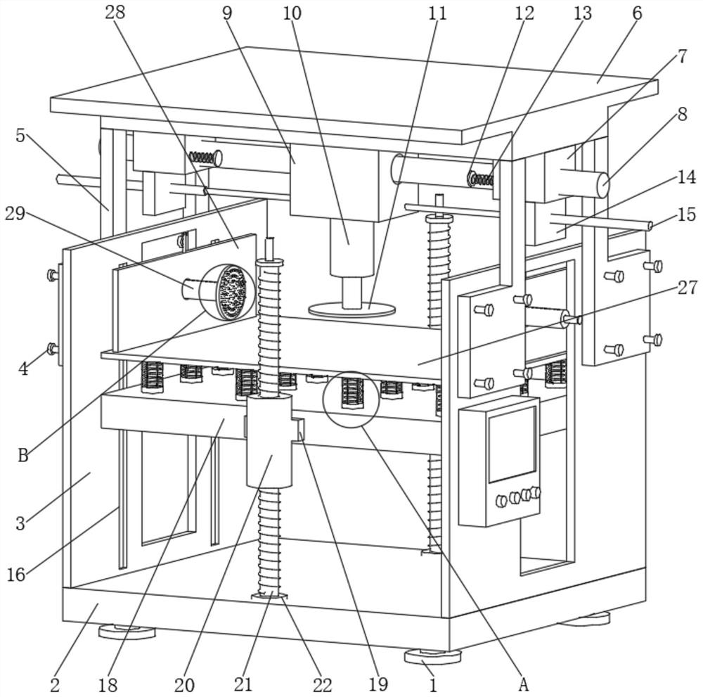
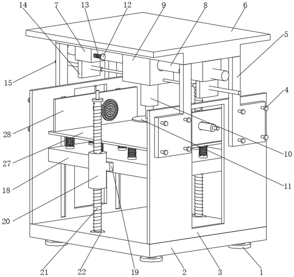
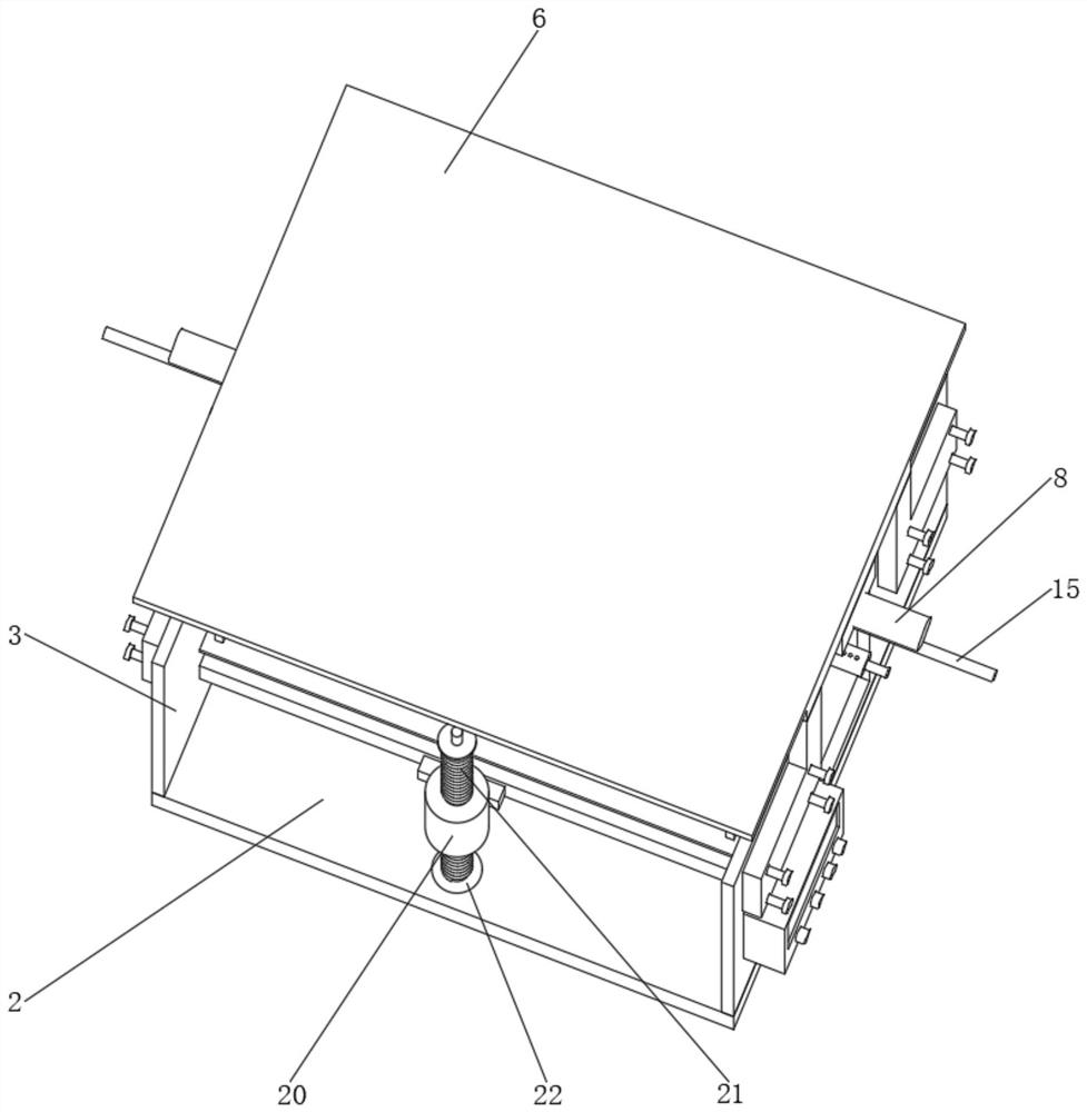
[0028] The following will clearly and completely describe the technical solutions in the embodiments of the present invention with reference to the accompanying drawings in the embodiments of the present invention. Obviously, the described embodiments are only some, not all, embodiments of the present invention. Based on the embodiments of the present invention, all other embodiments obtained by persons of ordinary skill in the art without making creative efforts belong to the protection scope of the present invention.

[0029] see Figure 1-7, the present invention provides a technical solution: a CNC tower stamping equipment, including foot 1, bottom plate 2, side plate 3, connecting nail 4, connecting plate 5, top plate 6, fixed plate 7, fixed shaft 8, driving seat 9. Stamping rod 10, pressing plate 11, damping plate 12, elastic spring 13, extension plate 14, electric telescopic rod 15, slide rail 16, slider 17, working plate 18, connecting block 19, threaded sleeve 20, scr...


PUM


Abstract

The invention belongs to the technical field of stamping equipment, and particularly discloses numerical control tray stamping equipment. The numerical control tray stamping equipment comprises ground feet and sliding rails, a bottom plate is arranged at the tops of the ground feet, side plates are arranged on the sides of the bottom plate, connecting nails are connected to the outer walls of the side plates, a connecting plate is arranged at the tops of the connecting nails, a top plate is arranged at the top of the connecting plate, a fixing plate is connected to the side of the top plate, a fixing shaft penetrates through the inner side of the fixing plate, a driving seat is mounted in the middle of the fixing shaft, a stamping rod is mounted at the bottom end of the driving seat, a pressing plate is arranged at the end of the stamping rod, a damping plate is arranged on the side of the driving seat, and an elastic spring is mounted at the end of the damping plate. According to the numerical control tray stamping equipment, a user can conveniently assemble and disassemble the parts of part stamping equipment, the automation degree of displacement of the parts of the equipment can be conveniently and further improved, and the user can conveniently and adaptively adjust and set the height position of a stamped part.

Description

technical field [0001] The invention relates to the technical field of stamping equipment, in particular to a numerically controlled tray stamping equipment. Background technique [0002] With the continuous development of industrial waste treatment technology, the structure and heat dissipation of stamping equipment still need to be improved, and the requirements for improving the functionality and convenience of stamping equipment are also increasing. The development of stamping equipment products must adapt to modern stamping equipment. Due to the requirements of quality development, multi-functional and convenient CNC tray stamping equipment has become a hot demand in the market. Therefore, a CNC tray stamping equipment is designed for this case. [0003] The existing stamping equipment on the market is inconvenient for users to assemble and disassemble the parts of the stamping equipment, to further improve the automation of device parts displacement, and to adjust the ...

Claims


Application Information

Patent Timeline
Patent Type & Authority Applications(China)
IPC IPC(8): B21D37/04B21D37/10B21D55/00B21D43/00
CPCB21D37/04B21D37/10B21D55/00B21D43/003
Inventor 不公告发明人
Owner 傅代伟
Why Eureka
Eureka Blog
Learn More