Paint dipping and drying integrated equipment

An integrated technology of dipping paint, applied to the device for coating liquid on the surface, pretreatment surface, spray device, etc., can solve the problems of low work efficiency, damage to the paint layer on the surface of the iron core, and cumbersome putting in and taking out. , to achieve the effect of improving production efficiency

Active Publication Date: 2021-06-11
FOSHAN CITY ZHONGYAN AMORPHOUS TECH
View PDF7 Cites 0 Cited by
  • Summary
  • Abstract
  • Description
  • Claims
  • Application Information

AI Technical Summary

Problems solved by technology

[0003] In the prior art, the dipping and drying processes usually need to be operated separately, that is, after the dipping is completed, the iron core needs to be transported to the drying furnace for drying. This method not only increases the manpower for iron core handling, but also It is very easy to damage the paint layer on the surface of the iron core, causing the paint surface to stick after drying. When entering the drying process, it needs to be reheated and baked from room temperature, resulting in waste of energy, which leads to low work efficiency. At the same time, the existing It is cumbersome to put in and take out the iron core by the paint dipping equipment, and the efficiency is low. Moreover, when the existing paint dipping equipment picks up the iron core and dips the paint, it is inevitable that the insulating paint cannot be soaked on the contact surface between the fixture and the iron core. The place where the paint is painted will also cause poor local insulation of the iron core. Now the high-frequency field has increasingly stringent requirements for the consistency and high reliability of the magnetic core. Only by mechanizing the production process and reducing manual work can it be achieved.

Method used


Image

  • Paint dipping and drying integrated equipment
  • Paint dipping and drying integrated equipment
  • Paint dipping and drying integrated equipment

Examples


Embodiment Construction

[0052] In order to make the objectives, technical solutions and beneficial effects of the present invention clearer, the technical solutions in the embodiments of the present invention will be clearly and completely described below in conjunction with the accompanying drawings in the embodiments of the present invention. Obviously, the described embodiments It is only some embodiments of the present invention, but not all embodiments.

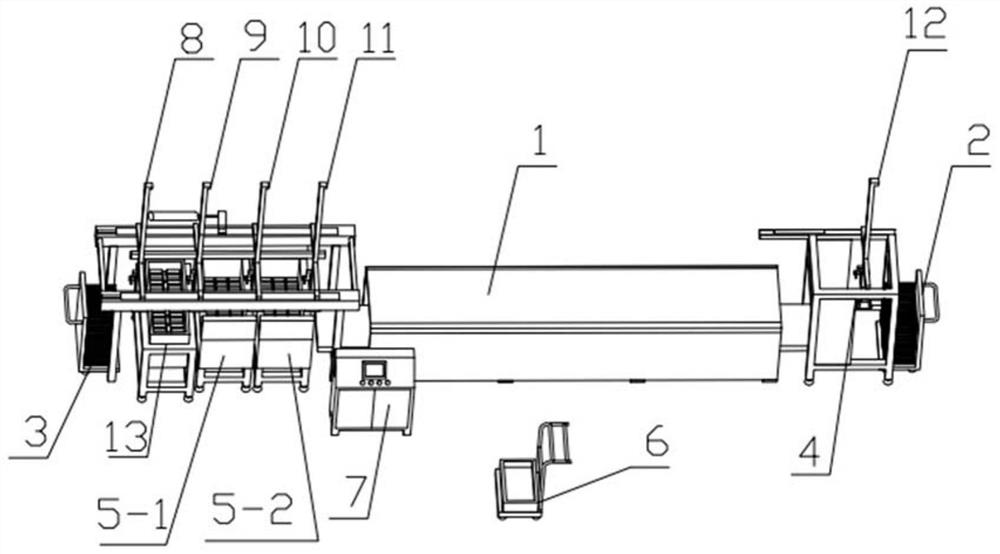
[0053] Such as figure 1 As shown, the integrated paint dipping and drying equipment includes iron core feeding and moving group mechanism 3, paint dipping device, air extraction device, electric control cabinet, drying device and unloading group mechanism 4, iron core feeding and moving group mechanism 3 is placed at the front end of the drying device, and the unloading group mechanism 4 is placed at the back end of the drying device. An electric control device is installed in the electric control cabinet, and the iron core feeding and moving g...


PUM


Abstract

The invention relates to the technical field of iron core paint dipping and drying, in particular to paint dipping and drying integrated equipment which comprises an iron core feeding moving group mechanism, a paint dipping device, an air extractor, an electric control cabinet, a drying device and a discharging group mechanism, wherein the iron core feeding moving group mechanism is arranged at the front end of the drying device, the discharging group mechanism is arranged at the rear end of the drying device, an electric control device is arranged in the electric control cabinet, the iron core feeding moving group mechanism comprises a manipulator group, and a paint dipping device and an air extractor are sequentially arranged below the manipulator group in the X-axis direction; and the manipulator group comprises a plurality of manipulator mechanisms. According to the invention, paint dipping and drying are separately realized at two stations, so that the assembly line type continuous operation can be realized, and the production efficiency is greatly improved. As the actual paint dipping time is very short, and the drying time is about twenty times of the paint dipping time, the baking mode is designed into net belt continuous baking, the whole equipment is long, and the production cost is reduced. And paint dipping and baking are separated, so that the work of removing a paint film generated by drying of the paint dipping box is omitted.

Description

technical field [0001] The invention relates to the technical field of iron core impregnation and drying, in particular to an integrated equipment for impregnation and drying. Background technique [0002] The iron core plays the role of converting magnetic energy into electrical energy and changing the voltage and current in the working engineering of the transformer. It is the core component of the transformer. The iron core is usually wound and stacked by soft magnetic materials such as silicon steel, amorphous, and nanocrystalline. , in the production process, in order to ensure its insulation performance, the iron core needs to be soaked in the insulating paint, and the paint is evenly infiltrated into each layer of the iron core, and then the drying process is carried out. Now the more immersion paint method is used. The vacuum impregnated paint is dried in a separate oven. [0003] In the prior art, the dipping and drying processes usually need to be operated separat...

Claims


Application Information

Patent Timeline
Patent Type & Authority Applications(China)
IPC IPC(8): B05C3/10B05C9/14B05C13/02B05D3/04B05C11/10B05B15/70
CPCB05C3/10B05C9/14B05C13/02B05D3/0413B05C11/10B05B15/70
Inventor 张志臻
Owner FOSHAN CITY ZHONGYAN AMORPHOUS TECH
Why Eureka
Try Eureka