
Garbage treatment equipment for building construction

A technology for waste treatment equipment and construction, applied in the field of waste treatment equipment for construction, can solve the problems of poor filtering effect, inability to achieve crushing effect, lack of auxiliary filtering by filter plates, etc., and achieve the effect of improving crushing effect

Inactive Publication Date: 2021-06-11
邹福全
View PDF12 Cites 4 Cited by
  • Summary
  • Abstract
  • Description
  • Claims
  • Application Information

AI Technical Summary

Problems solved by technology

However, the device lacks a variety of crushing parts, and only repeats the crushing of the garbage twice, which cannot achieve the expected crushing effect. Moreover, the device lacks auxiliary filtering parts for the filter plate, and the filtering effect is poor.

Method used


Image

  • Garbage treatment equipment for building construction
  • Garbage treatment equipment for building construction
  • Garbage treatment equipment for building construction

Examples


Embodiment 1

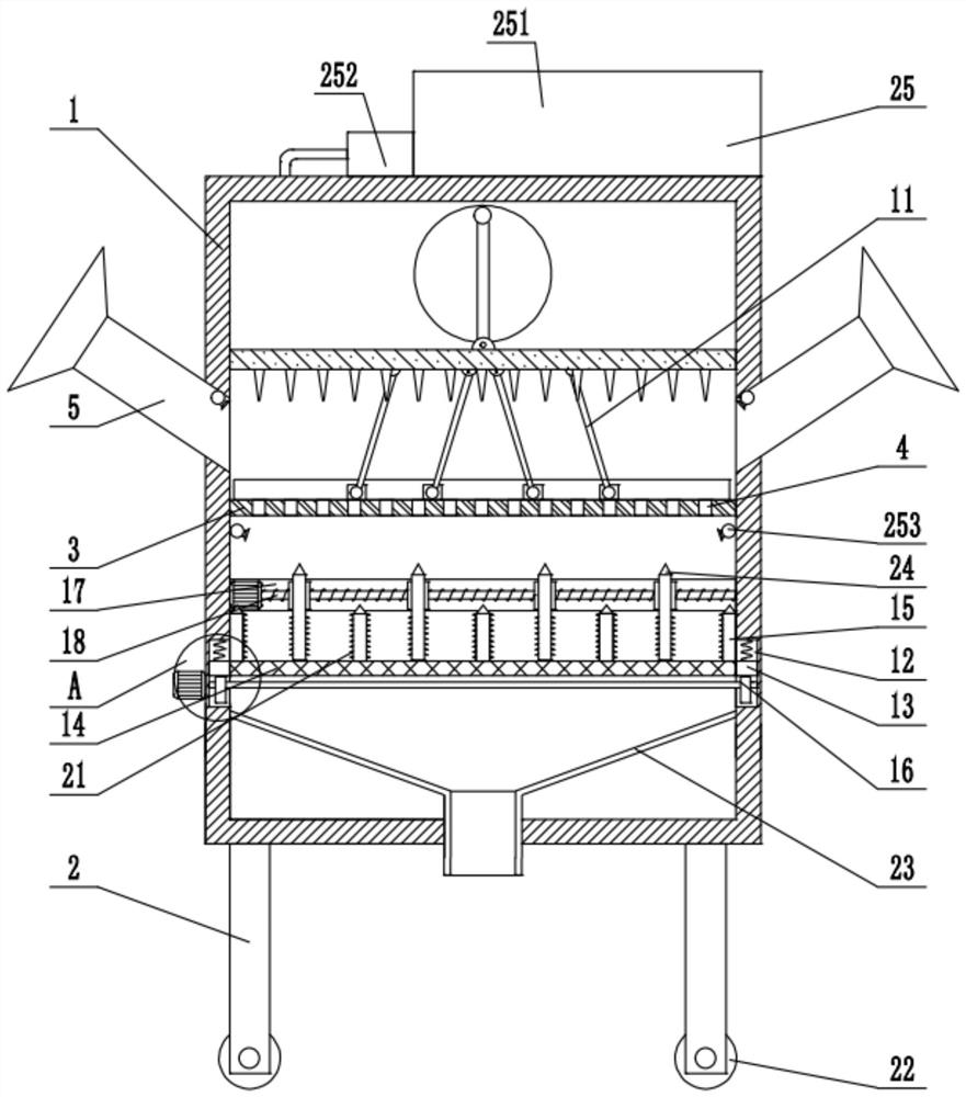
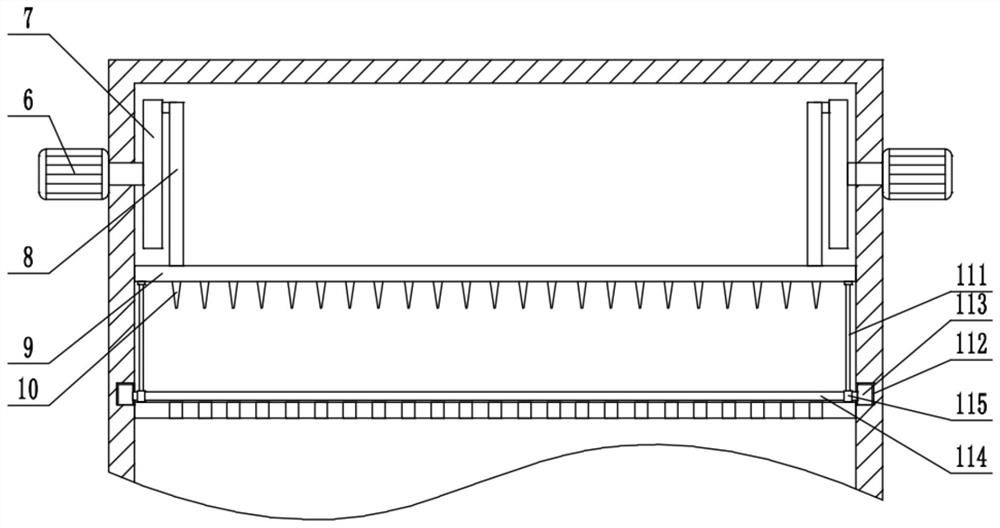
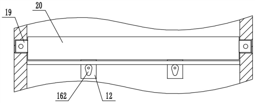
[0025] see Figure 1-5 , a kind of garbage treatment equipment for building construction, comprising a box body 1, support legs 2 are fixedly installed around the bottom of the box body 1, and inclined feed pipes extending into the box body 1 are fixedly installed on the left and right side walls of the box body 1 respectively 5. The first filter plate 3 is fixedly installed between the inner walls of the box body 1 below the feed pipe 5. There are multiple groups of filter holes 4 evenly distributed on the first filter plate 3, and the front and rear side walls of the box body 1 are respectively fixed. A motor 6 is installed, and the output shaft of the motor 6 extends into the box body 1 and is fixedly connected with a vertical rotating disk 7. Push-pull rods 8 are installed on the opposite side walls of the left and right two groups of rotating disks 7, respectively. The bottom ends of the rods 8 rotate together and are installed with a horizontal impact plate 9 that is sli...

Embodiment 2

[0027]On the basis of Embodiment 1, a roller 22 is mounted on the bottom of the supporting leg 2, and the position of the entire device is facilitated by the roller 22. The dust reduction component 25 includes a water tank 251 fixedly installed on the top of the box body 1, and the water tank 251 communicates with a fixed The pump machine 252 on the top of the box body 1, the pump machine 252 is connected with multiple sets of spray pipes 253 fixed between the inner walls of the box body 1, and the spray pipe 253 is fixedly equipped with multiple groups of atomizing nozzles distributed at equal intervals, and the material pushing parts 11 It includes the chute 112 opened on the side wall of the box body 1 on the front and rear sides of the first filter plate 3. There are multiple sets of sliders 113 slidingly installed in the chute 112, and the sliders 113 on the left and right sides are jointly connected with multiple sets of material shifting rods. 114, the left and right two...


PUM


Abstract

The invention belongs to the technical field of building construction, and discloses garbage treatment equipment for building construction. The equipment is technically characterized by comprising a box body, a first filter plate is fixedly mounted between the inner walls of the box body, motors are fixedly mounted on the front side wall and the back side wall of the box body, output shafts of the motors extend into the box body and are fixedly connected with vertical rotating discs, push-pull rods are rotationally mounted on the two opposite side walls of the left rotating disc and the right rotating disc, a horizontal impact plate glidingly connected with the inner wall of the box is rotationally mounted at the bottom ends of the left push-pull rod and the right push-pull rod jointly, multiple crushing cones evenly distributed at equal intervals are fixedly mounted at the bottom of the impact plate, a material shifting part is connected to the bottom of the impact plate, vertical grooves are formed in the left inner wall and the right inner wall of the box body below the first filter plate, mounting blocks are glidingly mounted in the vertical grooves, a second filter plate is fixedly mounted on the left mounting block and the right mounting block jointly, and multiple fixing plates distributed at equal intervals are fixedly mounted at the top of the second filter plate.

Description

technical field [0001] The invention relates to the technical field of building construction, in particular to garbage disposal equipment for building construction. Background technique [0002] Construction waste refers to the construction waste produced by man-made or natural reasons in the project, including waste slag, spoil, residual mud and waste materials, etc. These materials are of no help to the building itself, but are produced during the building process and need to be treated accordingly. Existing waste treatment equipment for building construction is usually only processed by a pair of crushing wheels. Therefore, due to the limitation of its structure, the crushing effect is not ideal, and secondary crushing is often required. [0003] In order to solve the above problems, the Chinese patent (notification number: CN 108889403 A, announcement date: 2018.11.27) discloses a waste disposal equipment for construction, which crushes the construction waste in the cru...

Claims


Application Information

Patent Timeline
Patent Type & Authority Applications(China)
IPC IPC(8): B02C21/02B02C1/14B02C1/00B02C23/14
CPCB02C21/02B02C1/14B02C1/00B02C23/14B02C2201/06
Inventor 邹福全
Owner 邹福全
Learn More