
Refractory material production system

A production system and technology of refractory materials, applied in loading/unloading, conveyors, grain processing, etc., can solve the problems of shortened labor time, inconvenient use of screening devices, etc., and achieve the effect of continuous and stable work

Inactive Publication Date: 2021-06-11
合肥惠嘉耐火材料有限公司
View PDF1 Cites 0 Cited by
  • Summary
  • Abstract
  • Description
  • Claims
  • Application Information

AI Technical Summary

Problems solved by technology

[0002] Chinese patent application, publication number is CN107499954A, a refractory material production system, the refractory material production system includes raw material crushing device, re-crushing device, screening device, ball milling device, iron remover, mixing device, forming device and kiln, the raw material crushing device is connected to the re-crushing device through the conveyor belt, the re-crushing device is connected to the sieving device through the conveyor belt, the sieving device is connected to the fan device through the conveyor belt, and the ball milling device is connected to the fan device through the conveyor belt. The iron remover is connected, the iron remover is connected with the material mixing device through the conveyor belt, the material mixing device is connected with the forming device through the conveyor belt, and the forming device is connected with the kiln through a tunnel; the refractory material proposed in this plan In the production system, conveyor belts are used to transport between various devices, which reduces the labor load and effectively shortens the time and improves work efficiency, but the sieving device is not convenient to use

Method used


Image

  • Refractory material production system
  • Refractory material production system
  • Refractory material production system

Examples


Embodiment 1

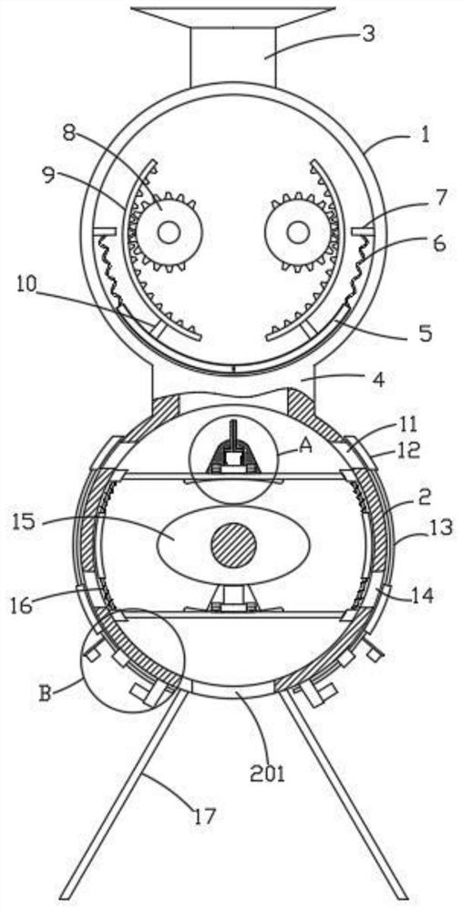
[0029] See Figure 1-5 , A refractory material production system includes a raw material crushing device, a re-crushing device, a screening device, a ball mill, an iron apparatus, a mixture apparatus, a molding apparatus, and a kiln.

[0030] The screening device includes a horizontal arrangement and a cylindrical storage cartridge 1 and a screen cartridge 2, and a tape 3 is disposed between the top of the storage cartridge 1, and the storage cartridge 1 and the sieve cartridge 2 are connected. 4 Connect, the batch sheet is provided in the storage cartridge 1 to allow the upper port of the connecting pipe 4 to be closed.

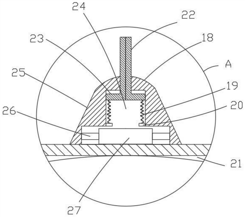
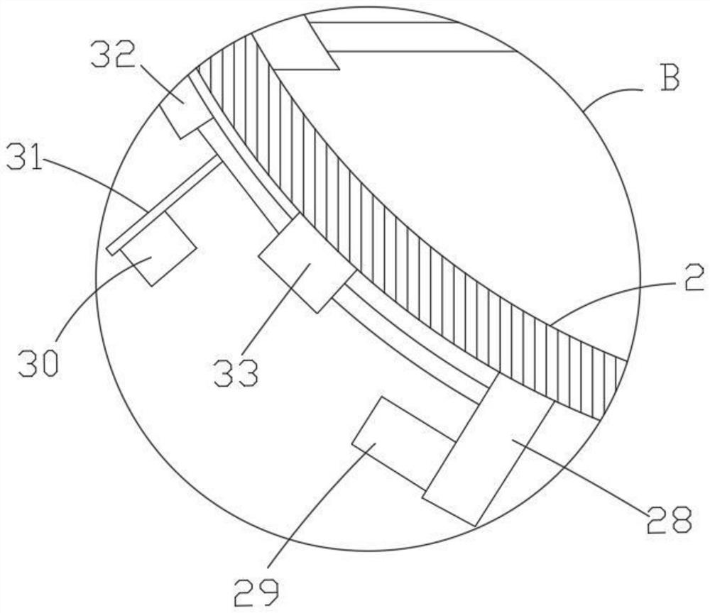
[0031] The screen discharge cartridge 2 is spaced apart from the two parallel sieve plates, and the two ends of the two screen plates are slidably connected in the inner wall of the screen cartridge 2, wherein the number of screen panels at the bottom is greater than the number of screen panels above, two The screening cartridge 2 is provided between the screen p...


PUM


Abstract

The invention relates to the technical field of refractory materials, and discloses a refractory material production system which comprises a raw material crushing device, a re-crushing device, a screening device, a ball milling device, an iron removal machine, a mixing device, a forming device and a kiln. The screening device comprises a storage barrel and a screening barrel which are arranged horizontally and are cylindrical; a feeding hopper is arranged on the top of the storage barrel, and the storage barrel and the screening barrel communicate with each other through a communicating pipe; an intermittent feeding mechanism is arranged in the storage barrel so that an upper end opening of the communicating pipe is intermittently opened and closed, and two parallel sieve plates are arranged in the screening barrel at intervals; the two ends of the two sieve plates are slidably connected with the inner wall of the screening barrel separately, wherein the number of the sieve plates located below is larger than that of the sieve plates located above; and a driving mechanism is arranged in the screening barrel between the two sieve plates, and used for driving the two sieve plates to vibrate. The refractory material production system is simple in structure, convenient in operation and stable and reliable in work, and facilitates screening of materials.

Description

Technical field [0001] The present invention relates to the field of refractory production technology, and more particularly to a refractory material production system. Background technique [0002] China Patent Application, Announced CN107499954A, a refractory material production system, the refractory material production system including raw material crushing means, re-crushing device, screwdriver, ball mill, iron apparatus, mixture device, molding device, The kiln, the raw material crushing device is connected to the re-crushing device through the conveyor belt, and the re-crushing means is connected to the screwdriver, and the screwdrion is connected to the fans by the conveyor belt. The ball milling device is passed through the conveyor belt. The iron machine is connected, and the iron machine is connected to the mixing device by the conveyor belt, and the mixing device is connected to the molded device through the conveyor belt, and the molding device is connected to the ki...

Claims


Application Information

Patent Timeline
IPC IPC(8): B02C21/00B02C23/14B65G65/30
CPCB02C21/00B02C23/14B65G65/30B65G2201/04
Inventor 许道海徐向峰
Owner 合肥惠嘉耐火材料有限公司
Learn More