
Measurement method and system of PET detector and computer readable storage medium

A measurement method and detector technology, applied in radiation measurement, measurement device, X/γ/cosmic radiation measurement, etc., can solve the problem of unpredictable PET system performance, time-consuming and labor-intensive, and more attention to single-channel performance. and other problems to achieve the effect of saving labor costs and time costs

Active Publication Date: 2021-06-08
FMI MEDICAL SYST CO LTD
View PDF12 Cites 0 Cited by
  • Summary
  • Abstract
  • Description
  • Claims
  • Application Information

AI Technical Summary

Problems solved by technology

[0003] However, there is currently no standard PET detector detection platform. The current mainstream detection method is to use an oscilloscope or a data acquisition card to manually collect data analysis results item by item according to specific measurement parameters. The whole process is time-consuming and labor-intensive, and the results are many Focus on single-channel performance
In the PET system, the performance of a single channel ultimately determines the performance of the entire system, but because the PET system has many channels (tens of thousands of channels), and because there are inconsistencies among scintillation crystals, photoelectric conversion devices and electronics, and PET detection The front-end electronics of the device often use a multiplexed circuit structure to reduce the complexity of the electronics, which leads to the performance of a single channel is often far better than the overall performance of the PET system, so only testing the performance of a single channel cannot predict the overall performance of a PET system

Method used


Image

  • Measurement method and system of PET detector and computer readable storage medium
  • Measurement method and system of PET detector and computer readable storage medium
  • Measurement method and system of PET detector and computer readable storage medium

Examples


Embodiment Construction

[0026] The advantages of the present invention will be further elaborated below in conjunction with the accompanying drawings and specific embodiments.

[0027] Reference will now be made in detail to the exemplary embodiments, examples of which are illustrated in the accompanying drawings. When the following description refers to the accompanying drawings, the same numerals in different drawings refer to the same or similar elements unless otherwise indicated. The implementations described in the following exemplary examples do not represent all implementations consistent with the present disclosure. Rather, they are merely examples of apparatuses and methods consistent with aspects of the present disclosure as recited in the appended claims.

[0028] The terminology used in the present disclosure is for the purpose of describing particular embodiments only, and is not intended to limit the present disclosure. As used in this disclosure and the appended claims, the singular f...


PUM


Abstract

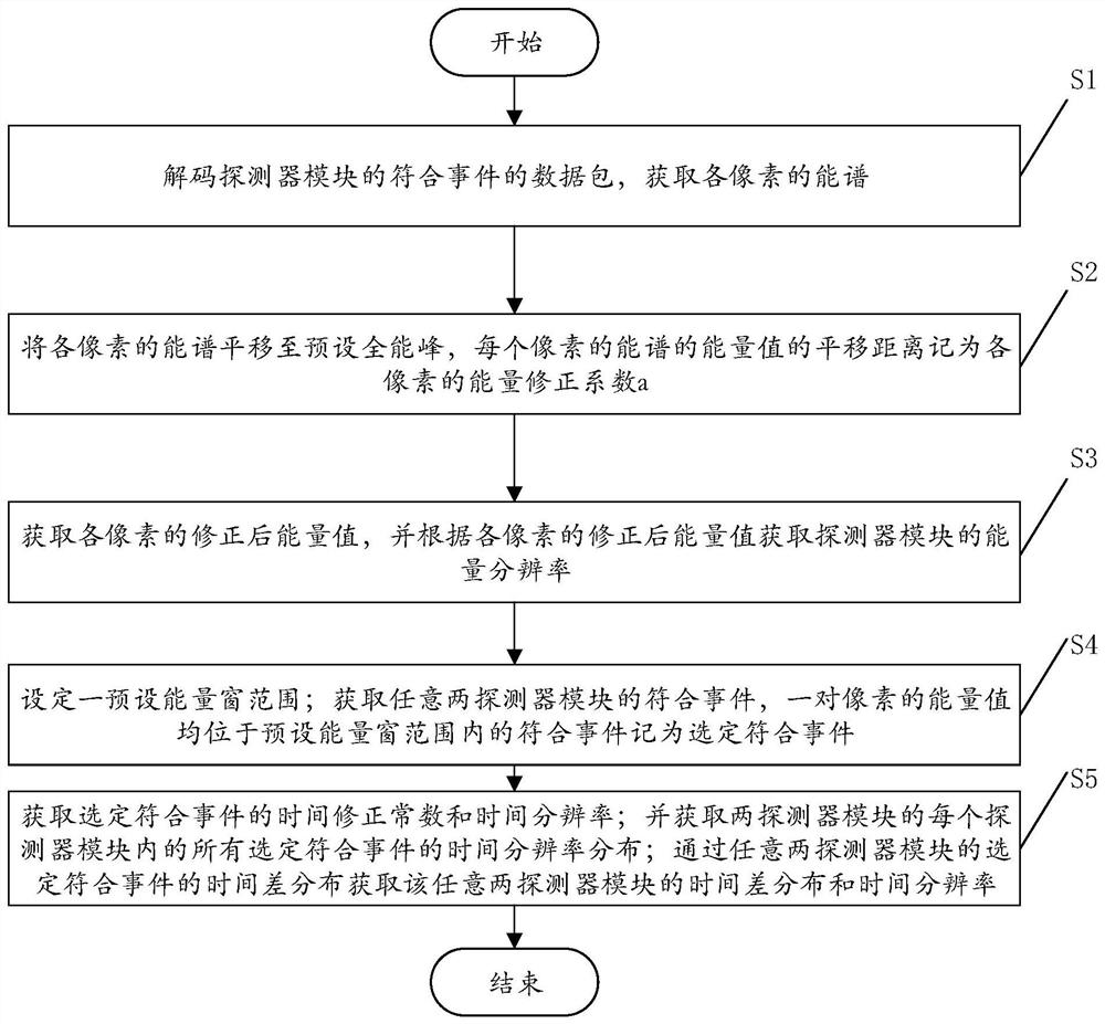
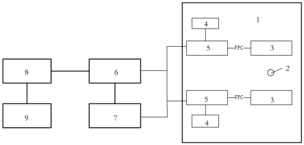
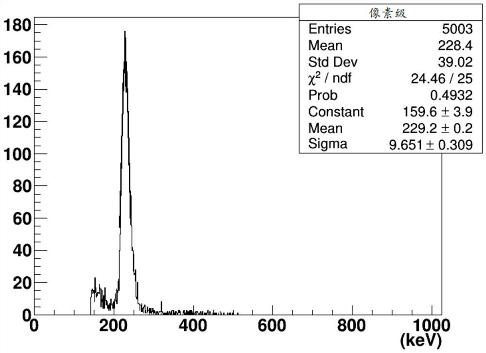
The invention provides a PET detector measurement method and system and a computer readable storage medium, electronic parameters are preset through an electronic measurement module, then coincidence data of two to-be-detected PET detector modules are measured, and finally analysis software is called to automatically analyze a measurement result, so that one-time acquisition can be realized. The time performance and the energy performance of the pixel level and the module level and the counting rate of the detector are automatically analyzed, and the performance of the module level detector is similar to the performance of the whole PET system, so that the performance of the whole PET system can be considered to be obtained. The method not only can be used for evaluating the intrinsic performance of the PET detector and detecting the coincidence performance of the two detectors, but also can be expanded to be used for detecting other radiation detectors, scintillation crystals and photoelectric conversion devices.

Description

technical field [0001] The present invention relates to the technical field of PET detectors, in particular to a measurement method, system and computer-readable storage medium for PET detectors. Background technique [0002] Positron Emission Tomography Scanner (PET) is a nuclear medicine imaging device, which is mainly composed of a detector system, an electronic system and a reconstruction system. The detector system consists of scintillation crystals, photoelectric conversion devices and front-end electronics. PET achieves tomographic imaging by collecting and judging a pair of gamma photons generated by a radioactive tracer injected into a living body. Simulate the electrical signal, and use the analog conditioning circuit to amplify the analog electrical signal and then measure the energy and arrival time information of the signal. By summarizing all the information measured by all detectors in the entire PET system, and rationalizing the information at the back end ...

Claims


Application Information

Patent Timeline
IPC IPC(8): G01T7/00G01T1/29A61B6/03
CPCG01T7/00G01T1/2985A61B6/037
Inventor 陈汉生赵晓坤李兴黄振强
Owner FMI MEDICAL SYST CO LTD
Learn More