Laser scanning device and angle measurement sensor and method based on laser scanning
A technology of laser scanning device and angle measuring sensor, which is applied in the direction of using optical devices, measuring devices, instruments, etc., and can solve problems such as difficult to meet the angle deflection range, stray light, and the influence of photodetector measurement results
- Summary
- Abstract
- Description
- Claims
- Application Information
AI Technical Summary
Problems solved by technology
Method used
Image
Examples
Embodiment 1
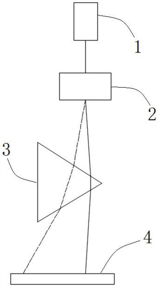
[0057] The present invention is realized through the following technical solutions, as figure 1 As shown, a laser scanning device is proposed, including a laser, a laser angle deflection device, a prism, and a laser measuring device, wherein:
[0058] A laser is used to emit a laser with a fixed wavelength to the laser angle deflection device;
[0059] The laser angle deflection device is used to change the exit angle of the laser emitted by the laser, and emit the laser with the changed exit angle to the prism;
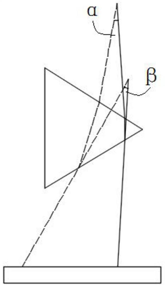
[0060] The prism is used to expand the angle of the laser light emitted by the laser angle deflection device, so that the angle between the two laser beams before and after the fixed time interval T increases;
[0061] The laser measuring device is used to receive the laser beam whose angle is enlarged by the triangular prism, and record the incident positions of the two laser beams before and after a fixed time interval T.
[0062] See figure 1 , where the solid ...
Embodiment 2
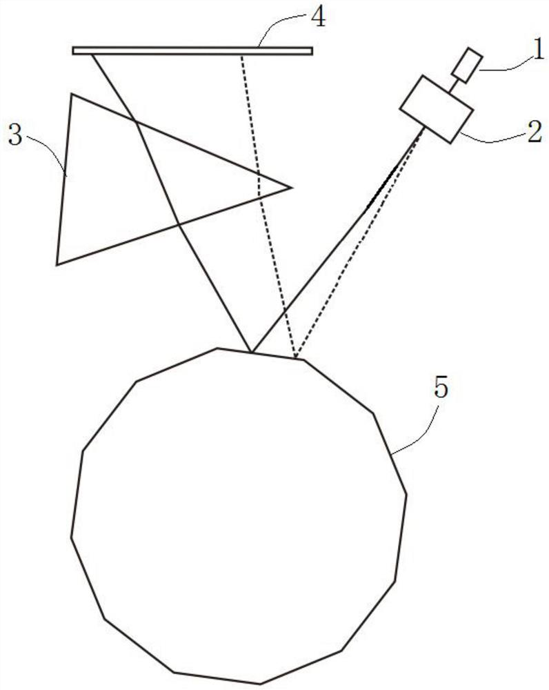
[0069] The present invention also proposes an angle measuring sensor based on laser scanning, including a measuring head and a polygonal regular prism. The measuring head includes a laser, a laser angle deflection device, a first prism, and a measuring photoelectric detector, wherein:
[0070] A laser is used to emit a laser with a fixed wavelength to the laser angle deflection device;
[0071] The laser angle deflection device is used to change the exit angle of the laser emitted by the laser, and emit the laser with the changed exit angle to the polygonal regular prism;
[0072] The first triangular prism is used to expand the angle of the laser light reflected by the polygonal regular prism, so that the angle between the two laser beams before and after the fixed time interval T increases;
[0073] The measurement photodetector is used to receive the laser light whose angle has been expanded by the first triangular prism, and record the incident positions of the two beams o...
Embodiment 3
[0087] The present invention also proposes a method for measuring angles based on laser scanning, comprising the following steps:
[0088] Step S1: at any time, the laser angle deflection device changes the exit angle of the laser emitted by the laser, and emits the laser with the changed exit angle to the polygonal regular prism, and the laser is reflected by the polygonal regular prism to the incident side of the first triangular prism, The first triangular prism changes the angle of the laser light, and transmits it to the measurement photodetector from its exit side, and at this time, the measurement photodetector records the incident position x1 of the laser light.
[0089] At this moment, the laser angle deflection device changes the exit angle of the laser emitted by the laser, and sends the laser with the changed exit angle to the beam splitter. side, the second triangular prism changes the angle of the laser light, and transmits it to the reference photodetector from it...
PUM
| Property | Measurement | Unit |
|---|---|---|
| angle of incidence | aaaaa | aaaaa |
| refractive index | aaaaa | aaaaa |
Abstract
Description
Claims
Application Information
 - R&D
- Intellectual Property
- Life Sciences
- Materials
- Tech Scout
- Unparalleled Data Quality
- Higher Quality Content
- 60% Fewer Hallucinations
Browse by: Latest US Patents, China's latest patents, Technical Efficacy Thesaurus, Application Domain, Technology Topic, Popular Technical Reports.
© 2025 PatSnap. All rights reserved.Legal|Privacy policy|Modern Slavery Act Transparency Statement|Sitemap|About US| Contact US: help@patsnap.com


