Flange sealing device

A flange sealing and flange technology, applied in the field of oil and gas production and transportation, can solve problems such as inability to eliminate leakage or puncture, puncture, affecting the efficiency of process pipeline production, etc.

Pending Publication Date: 2021-06-08
PETROCHINA CO LTD
View PDF0 Cites 0 Cited by
  • Summary
  • Abstract
  • Description
  • Claims
  • Application Information

AI Technical Summary

Problems solved by technology

[0003] After the process pipeline is put into production, when the temperature or pressure of the medium in the pipeline changes, or when the medium in the pipeline is highly corrosive, the sealing surface formed by the sealing steel ring and the sealing groove may be damaged. Leakage or puncture
In the prior art, when there is leakage or puncture at the sealing surface formed by the sealing steel ring and the sealing groove, the sealing steel ring will be further compressed by fastening the flange in order to restore the seal. When the method cannot eliminate the leakage or puncture, the sealing performance at the sealing surface formed by the sealing groove and the sealing steel ring can only be restored by replacing the flange piece or the sealing steel ring.
[0004] However, when replacing flanges or sealing steel rings, it is necessary to release the pressure of the pipeline, and even require industrial hot-fire and other operating procedures, which will cause the process pipeline to stop for a long time and seriously affect the production efficiency of the process pipeline.

Method used


Image

  • Flange sealing device
  • Flange sealing device
  • Flange sealing device

Examples


Embodiment Construction

[0040] In order to make the purpose, technical solutions and advantages of the embodiments of the present invention clearer, the technical solutions in the embodiments of the present invention will be clearly and completely described below in conjunction with the drawings in the embodiments of the present invention. Obviously, the described embodiments It is a part of embodiments of the present invention, but not all embodiments. Based on the embodiments of the present invention, all other embodiments obtained by persons of ordinary skill in the art without creative efforts fall within the protection scope of the present invention.

[0041] In the description of the present invention, it should be understood that the orientation or positional relationship indicated by the terms "top", "bottom", "upper", "lower" (if any) etc. is based on the orientation or positional relationship shown in the drawings , is only for the convenience of describing the present invention and simplif...


PUM


Abstract

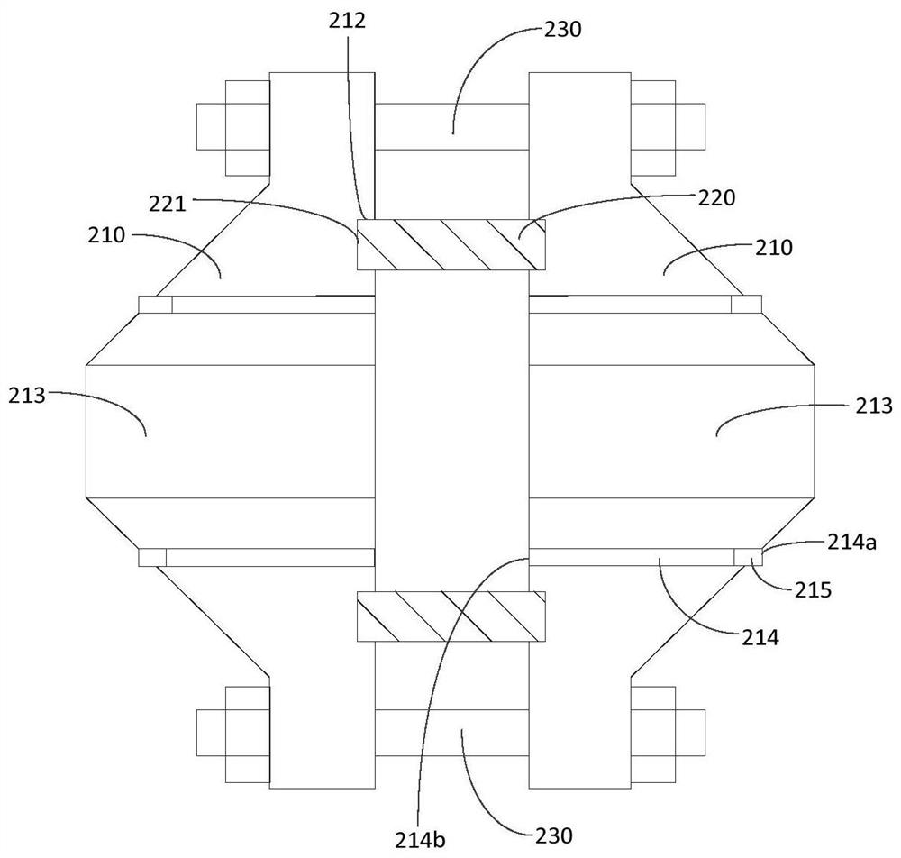
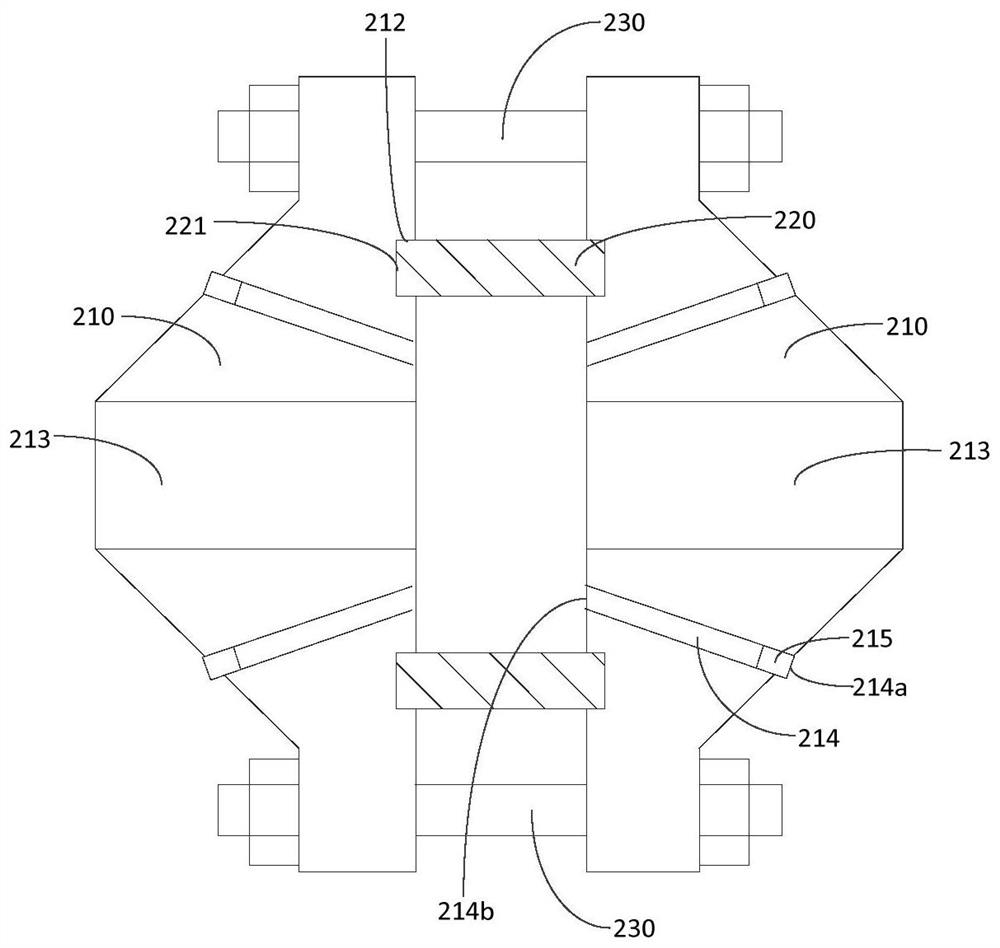
The invention provides a flange sealing device, which is applied to a process pipeline in an oil and gas field station. The flange sealing device comprises annular gaskets and two oppositely-arranged beveled flanges, wherein the annular gaskets are clamped between the two beveled flanges; each beveled flange has a first end and a second end; the first ends are used for being connected with a pipeline; the second ends of the two beveled flanges are oppositely arranged; annular sealing grooves capable of accommodating the annular gaskets are formed in the end faces of the second ends of the two beveled flanges; the beveled flanges are provided with grease injection channels; the grease injection channels are provided with grease inlets and grease outlets; the grease inlets are communicated with the outside; grease injection check valves are arranged at the grease inlets; and the grease outlets are formed between the annular sealing grooves and inner holes, and communicated with the joint of the annular sealing grooves and the annular gaskets, so that sealing grease flowing out of the grease outlets flows to the joint under the thrust action of a medium in the pipeline so as to seal the joint. The joint can be sealed under the condition that the process pipeline is not stopped, so that the production efficiency is ensured.

Description

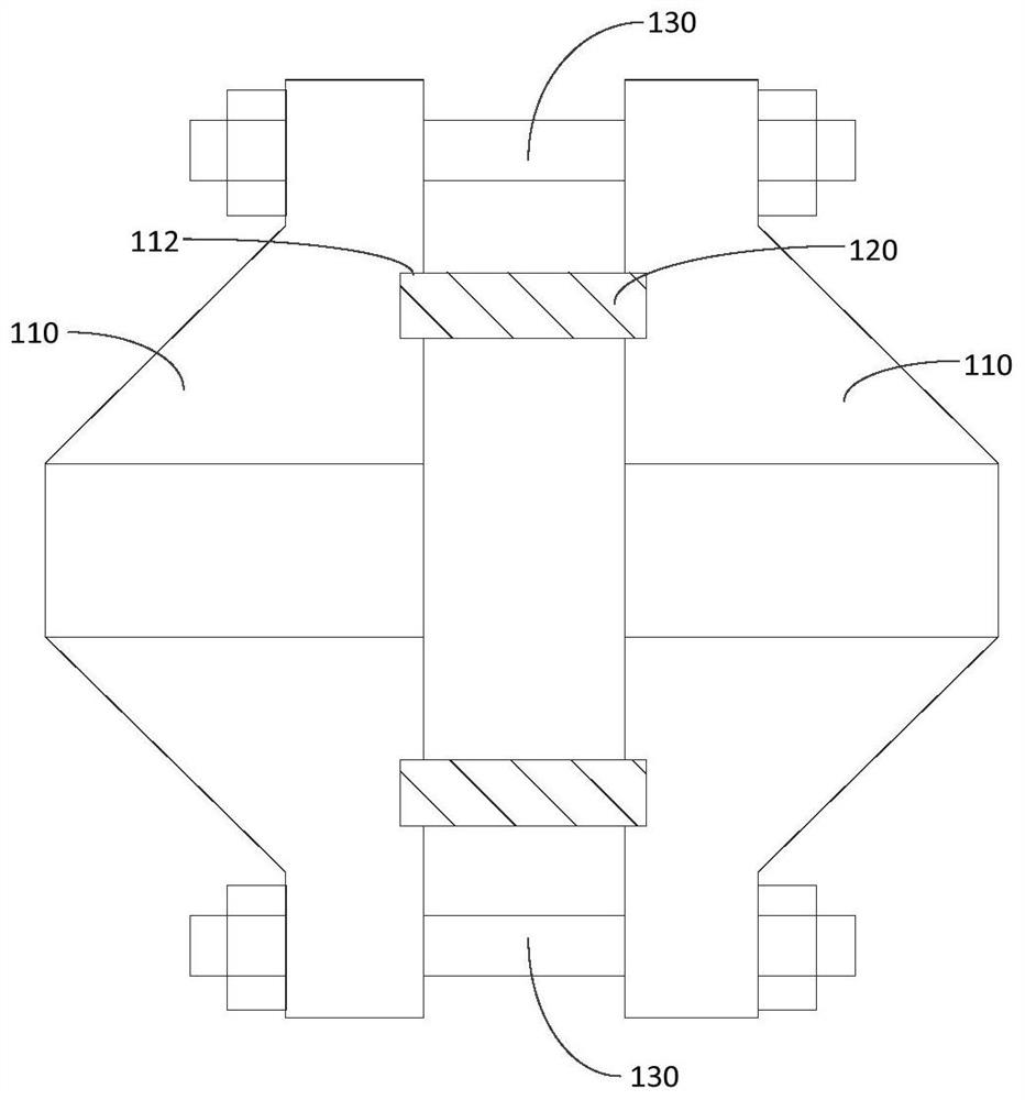
technical field [0001] The invention relates to the field of oil and gas exploitation and transportation, in particular to a flange sealing device. Background technique [0002] In order to meet the requirements of controlling the medium flow in the process pipeline in oil and gas stations, control valves or other devices are generally installed on different sections of the process pipeline. The control valve or other devices and the process pipeline need to pass through two grooves. Lan to dock to achieve the connection. see figure 1 As shown, in order to maintain good sealing performance and pressure bearing capacity after the process pipeline and the control valve or other devices are connected through two grooved flanges, it is usually provided on the butt joint surface of the two grooved flanges 110 Corresponding to the sealing groove 112, the sealing steel ring 120 is arranged between the two corresponding sealing grooves 112, and then the two groove flanges 110 are ...

Claims


Application Information

Patent Timeline
Patent Type & Authority Applications(China)
IPC IPC(8): F16L23/032F16L23/18
CPCF16L23/032F16L23/18
Inventor 朱昌军谭建华邹凯黄锟胡超韩占方杨刚张效东赵小军贾伟李原杰亢鞠
Owner PETROCHINA CO LTD
Why Eureka
Try Eureka