
Agricultural power mechanical device between rice fields

A technology for power machinery and agriculture, applied in the field of agricultural power machinery in paddy fields, can solve the problems of single structure, inflexibility, easy to be blocked by mud and water, low efficiency, etc.

Pending Publication Date: 2021-06-08
王琰
View PDF7 Cites 0 Cited by
  • Summary
  • Abstract
  • Description
  • Claims
  • Application Information

AI Technical Summary

Problems solved by technology

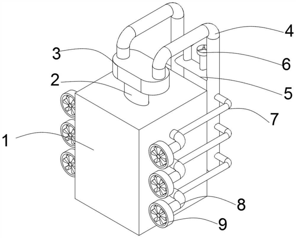
[0004] The purpose of the present invention is to provide a rice field agricultural power mechanical device, which solves the problem of low efficiency of the traditional rice field agricultural power mechanical device by setting a motor, a rotating shaft, a conveyor belt and a booster assembly, and sets a power supply box outside the power device Protecting and solving the problem that the traditional paddy field agricultural power machinery is easily blocked by muddy water. By setting up air filters and multiple power supply devices, the existing structure of the paddy field agricultural power machinery is single and not flexible enough.

Method used


Image

  • Agricultural power mechanical device between rice fields
  • Agricultural power mechanical device between rice fields
  • Agricultural power mechanical device between rice fields

Examples


Embodiment 1

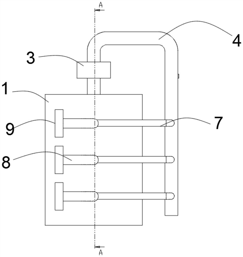
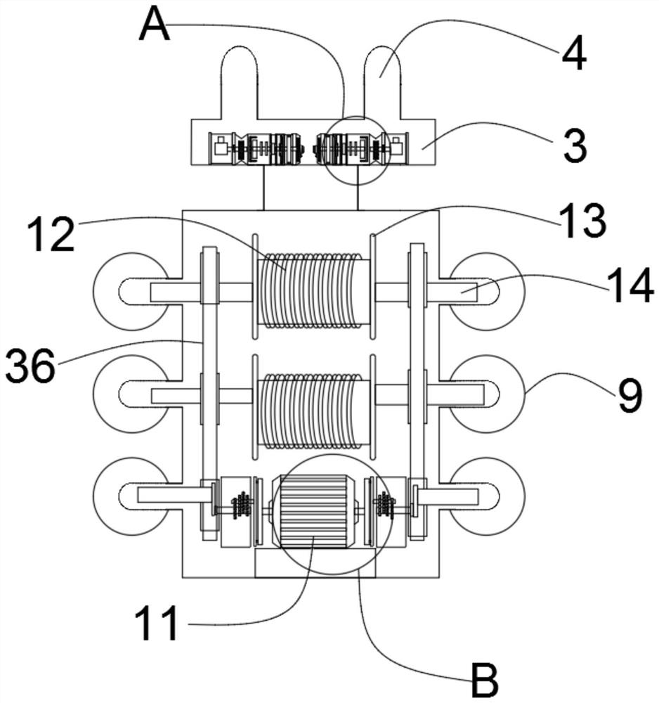
[0040] This embodiment is a method of using agricultural power machinery in rice fields: first, connect the power supply box 1 with the machinery that needs power supply, open the adjustable air pressure switch 15, and the air is under the action of the booster fan impeller 17 Carry out the first pressurization, and then through the speed-up gear box 19, further increase the air pressure, send the pressurized gas to the adjustable air filter 26, and output it to the pressurization pipe 4 through the pressurized airflow pipe 27, Turn on the pressurized air flow switch 6 and send it to the power turbine 9 for further pressurization to complete the provision of the first power.

Embodiment 2

[0042] It needs to be further explained that: in addition to the first power provided, there is also the second power provided by the motor 11. When the motor 11 rotates, the rotating shaft 29 also starts to rotate. According to the required power demand, through the adjustable speed torque gear Group 31, adjust its speed, the rotating shaft 29 drives the driven torque gear 32 to rotate, drives the power rotating shaft 14 to rotate, thereby drives the driving wheel 33 to start rotating, under the effect of the rotating belt 36, the first driven wheel 34 and the second The driven wheel 35 also starts to rotate, completing providing the second power for the power turbine 9 .


PUM


Abstract

The invention discloses an agricultural power mechanical device between rice fields, and relates to the technical field of power machinery. The device comprises a power supply box, the upper surface of the power supply box is provided with a pressurization air source seat, the upper surface of the pressurization air source seat is provided with a pressurization air source device, the upper surface of the pressurization air source device is provided with pressurization pipes, a connecting pipe is arranged between the pressurization pipes, and the upper surface of the connecting pipe is provided with a pressurization airflow switch and a decompression airflow switch; a second pressurization airflow pipe is arranged on the side face of the power supply box, and one end of the second pressurization airflow pipe is connected with a power turbine; and a motor and a rotating coil are arranged in the power supply box, power rotating cylinders are arranged at the two ends of the rotating coil and connected with power rotating shafts, driving wheels are arranged on the circumferential side faces of the power rotating shafts, and rotating belts are arranged on the circumferential side faces of the driving wheels. By arranging the pressurization airflow switch and the decompression airflow switch, the air pressure can be conveniently adjusted; and by arranging the power turbine, power can be conveniently provided for the device.

Description

technical field [0001] The invention belongs to the field of power machinery, in particular to a paddy field agricultural power machinery device. Background technique [0002] Agriculture is an industry that uses the growth and development laws of animals and plants to obtain products through artificial cultivation. Agriculture belongs to the primary industry, and the science that studies agriculture is agronomy. The objects of labor in agriculture are living animals and plants, and the products obtained are the animals and plants themselves. Agriculture is the basic industry that provides support for the construction and development of the national economy. The practice of precision agriculture in the world shows that the implementation of precision agriculture requires the integration and assembly of information technology, biotechnology, engineering equipment technology and management technology adapted to the market economy environment. Synthesis is its typical feature...

Claims


Application Information

Patent Timeline
IPC IPC(8): F01K27/00F01K13/00F01D15/00H02K7/10
CPCF01K27/00F01K13/00F01D15/00H02K7/1004
Inventor 王琰
Owner 王琰
Learn More