
Ground dry construction structure and construction method thereof

A dry method and ground technology, which is applied to floors, building structures, local raised floors, etc., can solve the problems of heavy pollution on the construction site, easy generation of large dust, and high labor costs, so as to shorten the construction period and reduce processing costs , the effect of reducing pollution

Pending Publication Date: 2021-06-08
璞勒仕建筑工程(上海)股份有限公司
View PDF8 Cites 0 Cited by
  • Summary
  • Abstract
  • Description
  • Claims
  • Application Information

AI Technical Summary

Problems solved by technology

[0003] The existing ceramic tiles are paved with cement mortar. In the actual application process, the process of cement mortar paving is complicated, the work efficiency is low, the labor cost is high, the pollution to the construction site is large, and a large amount of dust is easy to be generated.

Method used


Image

  • Ground dry construction structure and construction method thereof
  • Ground dry construction structure and construction method thereof
  • Ground dry construction structure and construction method thereof

Examples


Embodiment 1

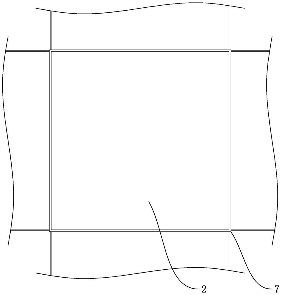
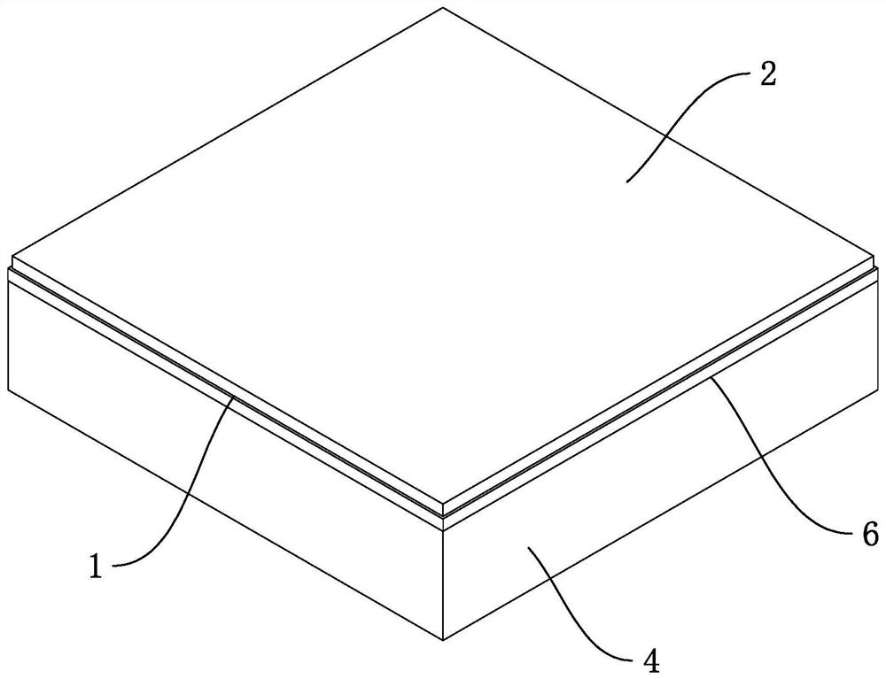
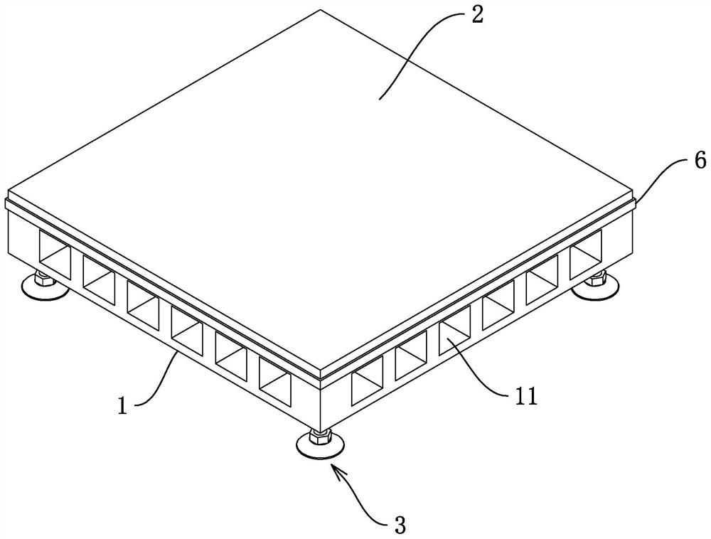
[0049] Such as figure 1 and figure 2 As shown, the ground dry construction structure includes a support body 1 and a panel layer 2 . Wherein, the panel layer 2 corresponds to the support body 1 one by one, the orthographic projections of the panel layer 2 and the support body 1 are equal, and the panel layer 2 is positioned and installed on the support body 1 . The supporting body 1 is laid on the structural base layer, and then foaming glue is injected between the panel layer 2 and the structural base layer. connected and fixed to form a floor structure laid on the structural base.

[0050] Through the foam rubber layer 4, the panel layer 2 is stably fixed on the structural base, and the formed floor structure can play the role of thermal insulation and sound insulation; due to the dry construction, it can shorten the construction period, effectively reduce the processing cost, and reduce the construction process. pollution of the environment.

[0051] Such as figure 2...

Embodiment 2

[0065] Such as Figure 7 and Figure 8 As shown, the difference between this embodiment and Embodiment 1 is that due to the principle of thermal expansion and contraction, usually, a certain gap should be reserved between the panel layers 2. In order to ensure the aesthetics of the floor laying, it is necessary to The gaps between adjacent panel layers 2 are made substantially equal. Each side of the support body 1 is fitted with at least two plug-in boards 5, and each side of the support body 1 is provided with a plug-in hole 13 corresponding to the plug-in boards 5, and the plug-in boards 5 are connected to the adjacent supports. The body 1 is plugged and fitted to ensure equal gaps between adjacent panel layers 2 .

[0066] continue as Figure 7 and Figure 8 As shown, in this embodiment, the plug board 5 is a plate-like structure made of plastic injection molding, and both ends of the plug board 5 are formed with plug parts that are mated with the support body 1, and t...


PUM


Abstract

The invention relates to a ground dry construction structure and a construction method thereof, and relates to the technical field of building decoration. The ground dry construction structure comprises supporting bodies, panel layers and foot stool assemblies, wherein the supporting bodies and the panel layers are arranged in a one-to-one correspondence mode and are in positioning fit, the foot stool assemblies are installed at the bottoms of the supporting bodies, the four corners of each supporting body correspond to the foot stool assemblies respectively, the foot stool assemblies adjust the positions of the supporting bodies, the foot stool assemblies are erected on a structural base layer, glue injection holes which communicate with each other are formed in each surface of the supporting bodies, foaming glue layers are arranged between the panel layers and the structural base layer, the foaming glue layers fix the panel layers on the structural base layer, and the panel layers are arranged at equal intervals. According to the ground dry construction structure and the construction method thereof, dry construction is adopted, so that the construction period is shortened, mortar pollution and volatile gas pollution are not generated in the construction process, the environment is protected, and the processing cost is reduced.

Description

technical field [0001] The present application relates to the technical field of building decoration, in particular to a ground dry construction structure and a construction method thereof. Background technique [0002] Traditional floor decoration usually adopts wet method, and the cement mortar concrete is leveled and then pasted with decorative surface materials. In recent years, various quick-installation systems have been widely used in interior decoration and ground decoration projects, such as installing keels on the ground, and veneering materials after wet methods. [0003] Existing ceramic tiles are paved with cement mortar. In the actual application process, the process of cement mortar paving is complex, low in efficiency, high in labor costs, heavy in pollution to the construction site, and prone to generate a large amount of dust. Contents of the invention [0004] In order to shorten the construction period of the ground, reduce processing costs, and reduce...

Claims


Application Information

Patent Timeline
IPC IPC(8): E04F15/02E04F15/024E04F15/08
CPCE04F15/02E04F15/02038E04F15/02405E04F15/02435E04F15/0247E04F15/082E04F2201/0523E04F2201/0547
Inventor 翁鸣
Owner 璞勒仕建筑工程(上海)股份有限公司
Learn More