Unmanned aerial vehicle for carrying expresses
A technology of unmanned aerial vehicles and airframes, which can be applied to unmanned aircraft, equipment for loading and unloading cargo, rotorcraft, etc., and can solve problems such as poor practicability and inability to classify express delivery
- Summary
- Abstract
- Description
- Claims
- Application Information
AI Technical Summary
Problems solved by technology
Method used
Image
Examples
Embodiment 1
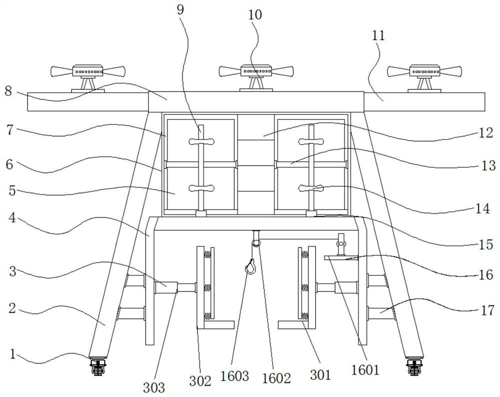
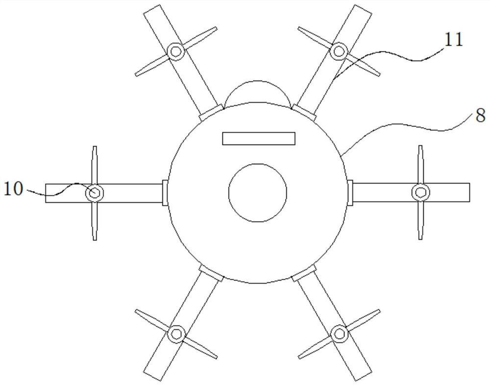
[0026] Example 1: See Figure 1-5 , an unmanned aerial vehicle for handling express delivery, including a lifting frame 2 and a fuselage 8, the four corners of the bottom end of the lifting frame 2 are respectively fixedly connected with the lifting frame 2, the bottom end of the lifting frame 2 is provided with mobile casters 1, and the body The bottom end of 8 is fixedly connected with placement shell 6, the exterior of fuselage 8 is fixedly connected with connecting rod 11, the top of connecting rod 11 is provided with propeller 10, and the middle position inside placing case 6 is provided with control module 12, and placing case 6 The bottom end of the connecting frame 4 is fixedly connected with the connecting frame 4, and the middle of the lifting frame 2 and the connecting frame 4 is fixedly connected with a connecting block 17. The top of one side of the connecting frame 4 is provided with a winding mechanism 16, and the two sides of the connecting frame 4 are provided ...
Embodiment 2
[0030] Embodiment 2: The limit mechanism 3 is composed of a load-bearing plate 301, a connecting plate 302, an electric telescopic rod 303, a buffer spring 304 and a limit plate 305. The electric telescopic rod 303 is fixedly connected to both sides of the connecting frame 4. The electric telescopic The model of the rod 303 is XTL50, one side of the electric telescopic rod 303 is fixedly connected with a connecting plate 302, the bottom end of one side of the connecting plate 302 is fixedly connected with a bearing plate 301, one side of the connecting plate 302 is provided with a limit plate 305, and the connecting plate A buffer spring 304 is fixedly connected between 302 and the limiting plate 305;
[0031] There are two groups of connecting plates 302, and the connecting plates 302 are symmetrically distributed with respect to the vertical center line of the connecting frame 4;
[0032] Specifically, such as figure 1 and Figure 4 As shown, when it is necessary to carry ...
Embodiment 3
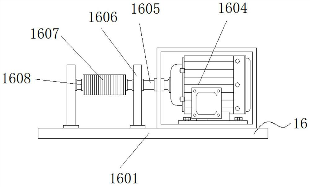
[0033]Embodiment 3: The winding mechanism 16 is composed of a support plate 1601, a movable roller 1602, a hook 1603, a servo motor 1604, a rotating shaft 1605, a support rod 1606, a suspension rope 1607 and a winding roller 1608, and the support plate 1601 is fixedly connected to the connecting frame 4. On the top of the inner side, the top end of the support plate 1601 is provided with a servo motor 1604. The model of the servo motor 1604 is MSME102GCCM. The output end of the servo motor 1604 is provided with a rotating shaft 1605, and the outer end of the rotating shaft 1605 is provided with a winding roller 1608 , the outside of the winding roller 1608 is provided with a suspension rope 1607, the bottom end of the suspension rope 1607 is fixedly connected with a suspension hook 1603, the movable roller 1602 is arranged at the top inside the connecting frame 4, and the other end of the top of the support plate 1601 is provided with a support rod 1606 ;
[0034] The suspensi...
PUM
 Abstract
Description
Claims
Application Information
 - R&D
- Intellectual Property
- Life Sciences
- Materials
- Tech Scout
- Unparalleled Data Quality
- Higher Quality Content
- 60% Fewer Hallucinations
Browse by: Latest US Patents, China's latest patents, Technical Efficacy Thesaurus, Application Domain, Technology Topic, Popular Technical Reports.
© 2025 PatSnap. All rights reserved.Legal|Privacy policy|Modern Slavery Act Transparency Statement|Sitemap|About US| Contact US: help@patsnap.com


