
Test tube shaking and mixing device for hematology department examination

A test tube and blood technology, which is applied in the field of test tube shaking and mixing devices for hematology testing, can solve the problems of low work efficiency and high labor intensity.

Inactive Publication Date: 2021-06-08
安徽昊天生物科技有限公司
View PDF0 Cites 1 Cited by
  • Summary
  • Abstract
  • Description
  • Claims
  • Application Information

AI Technical Summary

Problems solved by technology

[0004] The object of the present invention is to provide a test tube shaking and mixing device for hematological examination. Through the use of the rotating part, the supporting part and the fixed structure, it solves the problem of manually inverting the test tube for shaking and mixing after the existing hematological test, and the labor intensity is relatively high. Large, and when the number of people inspected is large, the work efficiency is low

Method used


Image

  • Test tube shaking and mixing device for hematology department examination
  • Test tube shaking and mixing device for hematology department examination
  • Test tube shaking and mixing device for hematology department examination

Examples


Embodiment 1

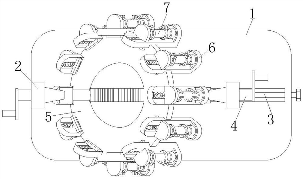
[0038] The use status of this embodiment is as Figure 8 As shown, rotating the threaded rod 3 drives one of the supporting rods 2 to move, and secondly, the supporting part 5 is clamped at the position between the two relative rotating parts 4. When clamping, the supporting disc 502 is perpendicular to the bottom plate 1. It is placed between two relative rotating parts 4 to ensure that the center of the sphere 501 coincides with the axis of the rotating shaft 401, and then the rotating threaded rod 3 drives the support rod 2 to move and then drives one of the rotating parts 4 to move to clamp the supporting part 5 Connected to the position between the two relative rotating parts 4, ensure that the first rack 403 on the sphere 501 is engaged with the second rack 504 that is fixedly connected to the inner surface of the arc plate 402 when clamping. After the overall fixation is completed, Move the extruding part 602 to shrink the compression spring 604, and the test tube 7 tha...

Embodiment 2

[0040] The use status of this embodiment is as figure 1 As shown, rotating the threaded rod 3 drives one of the supporting rods 2 to move, and secondly, the supporting part 5 is clamped at the position between the two relative rotating parts 4. When clamping, the supporting disc 502 and the bottom plate 1 form a certain angle. The position state is placed between the relative two rotating parts 4, and the angle range formed by the support disc 502 and the base plate 1 is 50°-140°. In this embodiment, the angle formed by the support disc 502 and the base plate 1 is 50°, ensure that the ball center of the sphere 501 coincides with the axis of the rotating shaft 401 when clamping, and then rotate the threaded rod 3 to drive the support rod 2 to move, and then drive one of the rotating parts 4 to move, and the supporting part 5 is clamped on the relative two rotating shafts. The position between the parts 4, ensure that the first rack 403 on the sphere 501 is engaged with the seco...


PUM


Abstract

The invention discloses a test tube shaking and mixing device for hematology department examination, and relates to the technical field of test tube shaking and mixing. The device comprises a bottom plate, a threaded rod rotationally matched with the bottom plate penetrates through one side face of the bottom plate, two supporting rods are arranged at the top of the bottom plate, the lower surface of one supporting rod is fixedly connected with the upper surface of the bottom plate, and the bottom of the other supporting rod is in transmission connection with the threaded rod; rotating parts are rotationally connected to the tops of the supporting rods, and supporting parts are clamped to the ends, opposite to the two rotating parts, of the supporting rods; each supporting part can rotate around the axis of the rotating part; the supporting part can rotate on the vertical plane where the axis of the rotating part is located; fixing structures are fixed on the outer surface of the supporting part at equal intervals, and test tubes are fixed on the fixing structures; and the rotating part comprises a rotating shaft. Through use of the rotating part, the supporting parts and the fixing structures, the problems that after examination in the hematology department, a test tube needs to be manually reversed to be shaken and mixed, the labor intensity of workers is high, and the working efficiency is low when the number of examiners is large are solved.

Description

technical field [0001] The invention belongs to the technical field of test tube shaking and mixing, in particular to a test tube shaking and mixing device for hematological examination. Background technique [0002] Blood drawing is the process of taking blood from the inside of a person's body for pathological analysis and then checking whether the person is suffering from a certain disease. For some patients, when using anticoagulant test tubes to draw blood, it is often necessary to shake the test tube after blood drawing to fully mix the blood with the anticoagulant so that the blood is difficult to coagulate and is convenient for inspection and analysis. [0003] The existing method of shaking and mixing the test tubes after blood drawing often uses manual shaking by inspectors to fully mix the blood and anticoagulant. The number of shaker test tubes is limited to 1 to 2 at most, and the work efficiency is low. Contents of the invention [0004] The object of the p...

Claims


Application Information

Patent Timeline
Patent Type & Authority Applications(China)
IPC IPC(8): B01F11/00B01F15/00
CPCB01F31/00B01F35/43B01F2101/23
Inventor 许常河
Owner 安徽昊天生物科技有限公司
Learn More