Shielding plate, terminal module using shielding plate and connector

A terminal module and shielding plate technology, which is applied in the direction of connection, parts and electrical components of the connection device, etc., can solve the problems of unreliable joints, difficult installation of shielding plates and shielding nets, etc., and achieves convenient processing or assembly. The effect of small, simplified structure

Active Publication Date: 2021-06-04
CHINA AVIATION OPTICAL-ELECTRICAL TECH CO LTD
View PDF8 Cites 0 Cited by
  • Summary
  • Abstract
  • Description
  • Claims
  • Application Information

AI Technical Summary

Problems solved by technology

[0004] The purpose of the present invention is to provide a shielding plate to solve the technical problems in the prior art that the shielding plate and the shielding net are difficult to install and the connection is not reliable; a terminal module and a connector using the shielding plate are also provided to solve The above technical issues

Method used


Image

  • Shielding plate, terminal module using shielding plate and connector
  • Shielding plate, terminal module using shielding plate and connector
  • Shielding plate, terminal module using shielding plate and connector

Examples


specific Embodiment 1

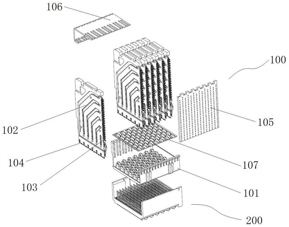
[0080] The connector of this embodiment is a female connector 100, such as figure 1 As shown, the structure of the connector assembly where the female end connector 100 is located is firstly introduced. The connector assembly includes a female end connector 100 and a male end connector 200 that are mated to each other. The end connectors 200 all have one end used for insertion as the front end. The female end connector 100 includes a female end housing 101 and a plurality of terminal modules 102 arranged on the female end housing 101, wherein the terminal module 102 has a mounting end 103 and a mating end 104, and the mounting end 103 is used for fixed installation on a printed circuit board. On the board, the mating end 104 is used for mating with the male end connector 200 . The terminal modules 102 are generally square plates, and the terminal modules 102 are arranged in sequence along the thickness direction of the terminal modules 102 .

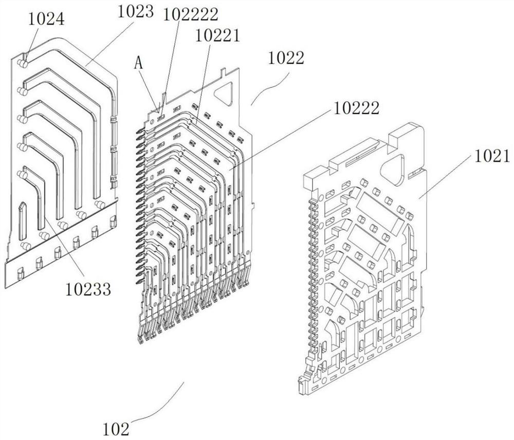
[0081] The structure of the ter...

specific Embodiment 2

[0112] like Figure 29 to Figure 32 As shown, the difference from Embodiment 1 is that in Embodiment 1, the guide slope is an inclined plane. In this embodiment, the guiding slope in the shielding plate 1023 is an arc-shaped surface 10238 , while the window 10237 between the convex shell 10232 and the main body 10231 , the way the shielding plate 1023 is connected to the ground terminal 10222 through the rivet 1024 remains unchanged.

Embodiment 1

[0114] In Embodiment 1, a shielding plate supporting protrusion is provided on the housing, and the shielding plate supporting protrusion cooperates with the differential pair partition wall to clamp the shielding plate. In this embodiment, the supporting protrusions of the shielding plate are eliminated. In order to prevent the shielding plate from moving, it is necessary to process the connection strength between the shielding plate and the insulator.


PUM


Abstract

The invention relates to a shielding plate and a terminal module using the shielding plate and a connector, the shielding plate takes one end facing a shielding net as a front end, the shielding plate comprises a main body part, an elastic convex part is arranged at the front end part of the main body part in a protruding manner, and the elastic convex part is a conductor connected with the main body part; and the elastic convex part is used for elastically abutting against the rear side face of the shielding net and is electrically connected with the shielding net. In the assembling process, the elastic convex part elastically abuts against the rear side face of the shielding net, and conductive communication between the main body part and the shielding net is achieved through the elastic protruding part. The shielding plate and the shielding net do not need to be sleeved and only need to be matched in a jacking manner, so that the mounting difficulty is low; and the elastic convex part is in elastic contact with the shielding net, so that the joint is firmer, the condition of virtual contact or non-contact is not easy to occur, and the shielding effect is enhanced.

Description

technical field [0001] The invention relates to a shielding plate, a terminal module and a connector using the shielding plate. Background technique [0002] The connector in the prior art includes a housing and a terminal module assembled on the housing, wherein the terminal module has a mating end as the front end, the terminal module includes an insulator and a terminal part and a shielding plate arranged on the insulator, and the terminal part includes A ground terminal and a differential pair, the differential pair includes two signal terminals. Wherein, the shielding plate is in electrical contact with the grounding terminal in the same terminal module to realize overall shielding. In order to ensure that the signal of the connector has a good return path and less crosstalk, improve the signal return, and enhance the electromagnetic isolation effect, a shielding net is fixed on the housing, and the shielding net is provided with signal perforations and grounding perfo...

Claims


Application Information

Patent Timeline
Patent Type & Authority Applications(China)
IPC IPC(8): H01R13/6581
CPCH01R13/6581
Inventor 李宗蔚
Owner CHINA AVIATION OPTICAL-ELECTRICAL TECH CO LTD
Why Eureka
Try Eureka