
Hydraulic vibration tamping plate for preventing clay for small excavator

A hydraulic vibration and excavator technology, which is applied in the field of hydraulic vibration rammers, can solve problems such as easy adhesion of soil and poor compacting effect of ramming plates, and achieve the effect of reducing labor load

Inactive Publication Date: 2021-06-04
嘉兴佳茂商贸有限公司
View PDF0 Cites 0 Cited by
  • Summary
  • Abstract
  • Description
  • Claims
  • Application Information

AI Technical Summary

Problems solved by technology

[0005] Aiming at the deficiencies of the prior art, the present invention provides a hydraulic vibration ramming plate for a small excavator to prevent clay, which has the advantages of good tamping effect on the ground and no need to frequently clean the soil on the bottom wall of the ramming plate, which solves the problem of traditional vibration The bottom wall of the tamping plate is easy to adhere to the soil, which leads to poor compaction effect of the tamping plate and the need for frequent cleaning

Method used


Image

  • Hydraulic vibration tamping plate for preventing clay for small excavator
  • Hydraulic vibration tamping plate for preventing clay for small excavator
  • Hydraulic vibration tamping plate for preventing clay for small excavator

Examples


Embodiment Construction

[0026] The following will clearly and completely describe the technical solutions in the embodiments of the present invention with reference to the accompanying drawings in the embodiments of the present invention. Obviously, the described embodiments are only some, not all, embodiments of the present invention. Based on the embodiments of the present invention, all other embodiments obtained by persons of ordinary skill in the art without making creative efforts belong to the protection scope of the present invention.

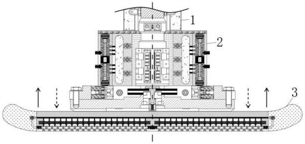
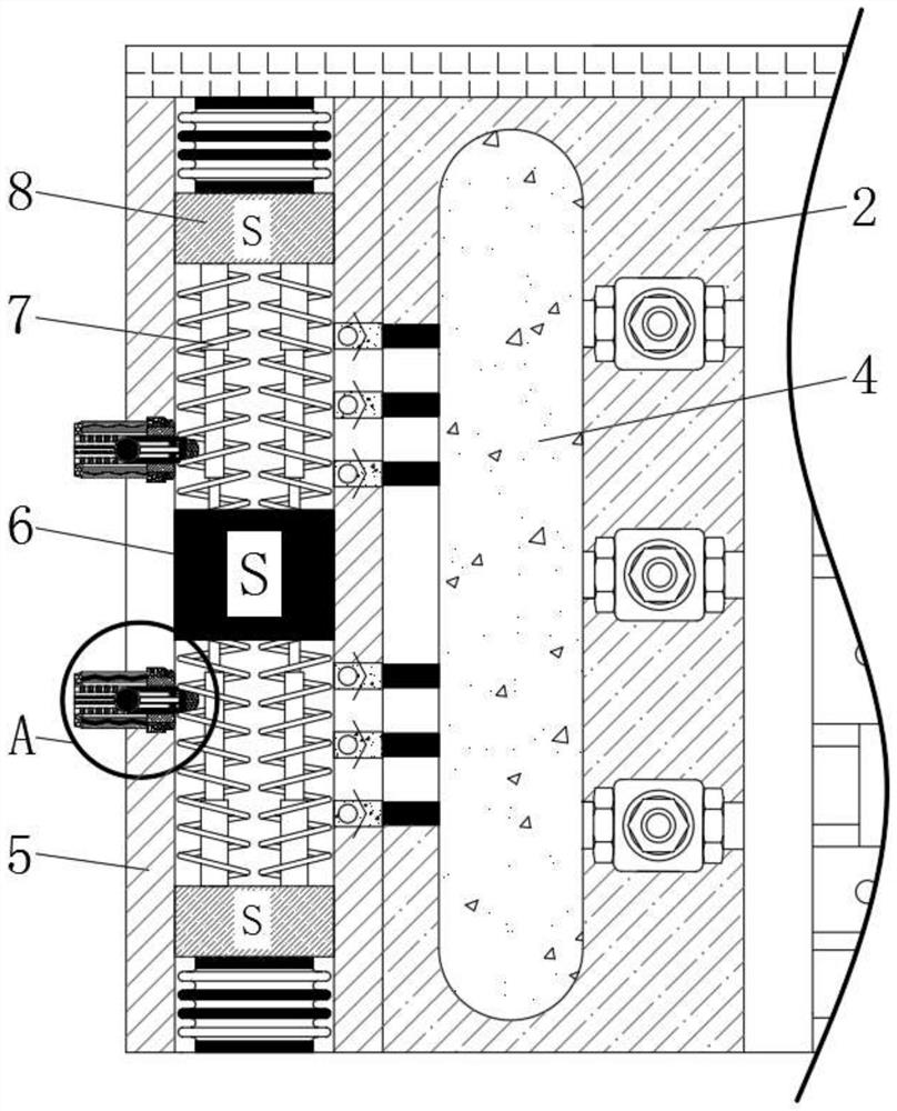
[0027] see Figure 1-6 , a hydraulic vibrating tamping plate used for small excavators to prevent clay, including a hydraulic drive shaft 1, the top end of the hydraulic drive shaft 1 is connected to the hydraulic pump of the excavator, and the bottom end of the hydraulic drive shaft 1 slides with the fixed seat 2 Connection, the bottom end of the hydraulic drive shaft 1 is movably connected with a fixed seat 2, the interior of the fixed seat 2 is fixedly conn...


PUM


Abstract

The invention relates to the technical field of hydraulic vibration tamping, and discloses a hydraulic vibration tamping plate for preventing clay for a small excavator. The hydraulic vibration tamping plate comprises a hydraulic driving shaft, wherein the bottom end of the hydraulic driving shaft is movably connected with a fixing seat, an inflation bin is fixedly connected to the interior of the fixing seat, an electromagnetic block is fixedly connected to the inner wall of the inflation bin, and a spring rod is fixedly connected to the outer wall of the electromagnetic block. According to the hydraulic vibration tamping plate for preventing the clay for the small excavator, the clay entering a cleaning groove is scraped off when a baffle slides, so that the adhesion area of the clay on the bottom wall of the tamping plate is reduced; and when the baffle is meshed with a through groove in the inner wall and the cleaning groove, a water source in a high-pressure spray head is rapidly sprayed out under the pressurization of an air guide pipe, the high-pressure water source blows up the clay adhered in the cleaning groove, the clay in the cleaning groove drives the bottom wall of the tamping plate and the clay adhered to the bottom wall of the tamping plate together when the clay falls off, so that the situation that the tamping plate cannot uniformly tamp the ground due to the fact that the clay is adhered to the bottom surface of the tamping plate for a long time is avoided.

Description

technical field [0001] The invention relates to the technical field of hydraulic vibrating rammers, in particular to a hydraulic vibrating rammer plate used for preventing clay in small excavators. Background technique [0002] The vibrating rammer belongs to the matching equipment of the excavator and is used to tamp the ground. It can tamp planes, slopes, steps, grooves, pits, corners, abutment backs, etc. It is widely used in the compaction industry, and the applicability of the vibrating rammer is strong. , often instead of vibratory rollers for construction in some small areas. [0003] When the hydraulic vibratory rammer tamps some ground with high cohesion and friction, the soil on the ground is easy to adhere to the bottom wall of the tamping plate. When the tamping plate tamps other areas, the bottom wall adheres The soil is easy to cause uneven force on the ramming plate, which makes it impossible for the ramming plate to tamp the ground evenly. The soil adhered t...

Claims


Application Information

Patent Timeline
Patent Type & Authority Applications(China)
IPC IPC(8): E02F5/30E02D3/068B08B1/00B08B3/02
CPCE02F5/30E02D3/068B08B3/02B08B1/165
Inventor 陈旗
Owner 嘉兴佳茂商贸有限公司
Learn More