A drive wheel independent damping structure of an agv drive assembly

A driving assembly and driving wheel technology, applied in the direction of vehicle springs, elastic suspensions, vehicle components, etc., can solve the problems of AGV body unable to lift synchronously, unable to provide axial buffering, AGV tipping, etc., to increase thickness, ensure Stability, the effect of increasing the load-bearing capacity

Active Publication Date: 2022-03-22
ZHEJIANG FIELD INTELLIGENT EQUIP CO LTD
View PDF8 Cites 0 Cited by
  • Summary
  • Abstract
  • Description
  • Claims
  • Application Information

AI Technical Summary

Problems solved by technology

[0004] Using the above-mentioned independent shock absorbing structure, there are still the following deficiencies: 1. The support beam is connected to the AGV, the drive wheel mounting plate and the support beam are hingedly arranged, and the drive wheels are arranged on both sides of the drive wheel mounting plate, and then the support beam and the drive wheel An independent cushioning structure is set between the mounting plates, the purpose of which is not to change the position of the driving wheel when the AGV body is raised and lowered. However, the setting of its hinge determines that the AGV body cannot move up and down synchronously when it is stressed, and can only move away from the hinge point. If the AGV is transporting the goods, it will cause the goods to dump out, otherwise it is necessary to set up another mechanism to avoid the dumping of the goods, which obviously needs to be improved; 2. The above settings can only perform longitudinal buffering, but cannot Provide axial cushioning. When the AGV body is subjected to axial impact, because it is integrated with the drive assembly below, when the force is transmitted to the drive assembly, the drive assembly cannot provide axial cushioning, which may easily cause the AGV to fall or damaged

Method used


Image

  • A drive wheel independent damping structure of an agv drive assembly
  • A drive wheel independent damping structure of an agv drive assembly
  • A drive wheel independent damping structure of an agv drive assembly

Examples


Embodiment

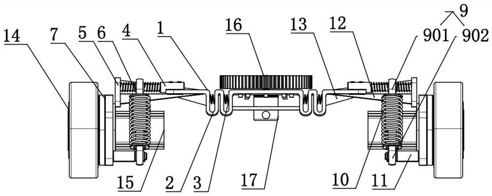
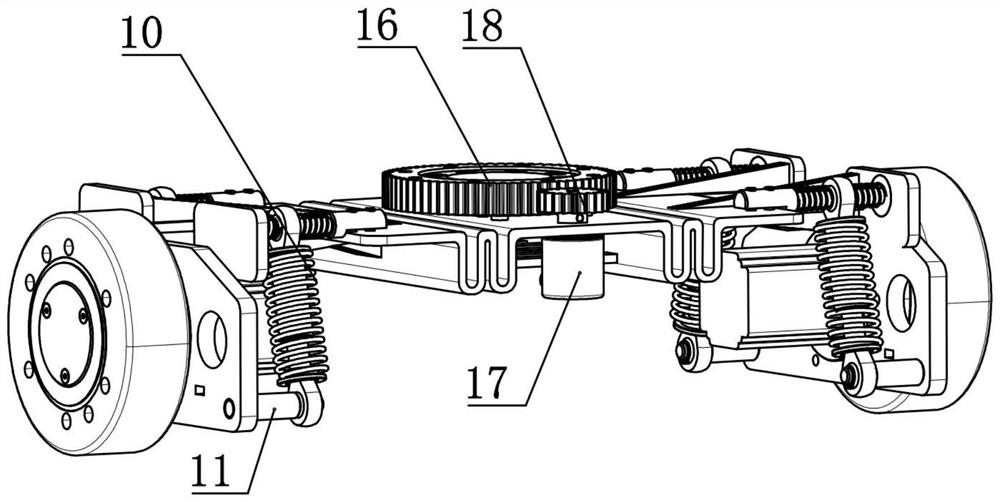
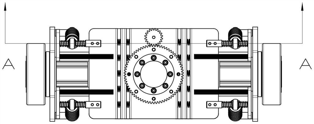
[0029] A drive wheel independent damping structure of an AGV drive assembly, refer to Figure 1-Figure 6 As shown, it includes a support plate 1 fixedly connected to the bottom plate 8 of the AGV body, a drive plate 7 positioned on both sides of the support plate 1, a drive wheel 14 mounted on the drive plate 7, and a first motor 15 that drives the drive wheel 14 to rotate, The driving wheel 14 is rotationally connected with the driving plate 7 through a rotating shaft, the first motor 15 is fixed on the inner surface of the driving plate 7, the first motor shaft is fixedly connected with the rotating shaft, and a fixed connection with the base plate 8 is arranged on the upper end surface of the support plate 1 for rotation. The driven gear 16 is provided with a driving gear 18 meshing with the driven gear 16 on the support plate 1, and a second motor 17 that drives the driving gear 18 to rotate is fixed on the lower end surface of the support plate 1. When the controller recei...


PUM


Abstract

The invention relates to the field of AGV technology, and discloses an independent damping structure for driving wheels of an AGV drive assembly, including a support plate, a drive plate, a drive wheel, and a first motor for driving the drive wheel to rotate. Longitudinal buffer structure, the longitudinal buffer structure includes elastic compression buffer parts respectively arranged at both ends of the side opposite to the support plate and the drive plate, the upper and lower ends of the elastic compression buffer parts are respectively fixed with the support plate and the drive plate, between the support plate and the elastic compression An axial buffer structure is arranged between the buffer parts, and the axial buffer structure includes a buffer shaft fixed outwardly on both sides of the support plate and interspersed with the elastic compression buffer part, and a limit plate provided at the end of the buffer shaft away from the support plate And on the buffer shaft, the first buffer springs that are socketed on both sides of the elastically compressed buffer part are elastically contacted with the support plate or the limit plate. This independent shock absorbing structure can significantly improve the AGV's shock resistance, anti-dumping performance and Impact resistance.

Description

technical field [0001] The invention relates to the field of AGV technology, in particular to an independent damping structure of a driving wheel of an AGV driving assembly. Background technique [0002] AGV is the abbreviation of Automated Guided Vehicle, which means "automatic guided transport vehicle". AGV is a transport vehicle equipped with automatic guidance devices such as electromagnetic or optical, capable of driving along the prescribed guidance path, with safety protection and various transfer functions. [0003] During the operation of the AGV, the stability determines the performance of its transported goods. The Chinese patent with the notification number CN211684556U discloses an independent damping structure for the driving wheel of the AGV differential drive assembly, including the AGV body, and the AGV body is arranged on the support beam. , the support beam is provided with a fulcrum shaft, the fulcrum shaft is also connected with a drive wheel mounting p...

Claims


Application Information

Patent Timeline
Patent Type & Authority Patents(China)
IPC IPC(8): B60G11/56
CPCB60G11/56B60G2202/12B60G2202/152
Inventor 柯德莉方朱峰汪庭兵方欣琛于浩源潘荆栋
Owner ZHEJIANG FIELD INTELLIGENT EQUIP CO LTD
Why Eureka
Try Eureka