Eureka AIR delivers breakthrough ideas for toughest innovation challenges, trusted by R&D personnel around the world.

Hot fluid pipeline full-ceramic electric heating body heating control device

A control device and thermal fluid technology, which are applied in the directions of cleaning methods, chemical instruments and methods, cleaning methods and utensils using gas flow, etc., which can solve the problem of increasing the work intensity of users, affecting the heat dissipation of electrical components, and damaging the electrical components of operation cabinets, etc. question

Inactive Publication Date: 2021-06-04
ZHICHENG JIN TECH
View PDF3 Cites 1 Cited by
  • Summary
  • Abstract
  • Description
  • Claims
  • Application Information

AI Technical Summary

Problems solved by technology

[0003] Usually, the control devices used to heat the fluid in the pipeline are installed in an operation cabinet, so that the user can control the temperature of the heating pipeline by setting the program. When the heating device is working, the electrical components in the operation cabinet also work. A lot of heat will be generated during use, but the heat dissipation of existing operation cabinets usually requires the user to open the door to ventilate when he feels the heat. Due to the work intensity of the user, and the neglect of ventilation due to negligence, the electrical components in the operation cabinet are easily damaged due to high temperature, and because some dust will accumulate on the electrical components, these dust layers will adhere to the electrical components, which will also affect the heat dissipation of the electrical components.

Method used


Image

  • Hot fluid pipeline full-ceramic electric heating body heating control device
  • Hot fluid pipeline full-ceramic electric heating body heating control device
  • Hot fluid pipeline full-ceramic electric heating body heating control device

Examples


Embodiment Construction

[0025] The following will clearly and completely describe the technical solutions in the embodiments of the present invention with reference to the accompanying drawings in the embodiments of the present invention. Obviously, the described embodiments are only some, not all, embodiments of the present invention.

[0026] In describing the present invention, it should be understood that the terms "center", "longitudinal", "transverse", "length", "width", "thickness", "upper", "lower", "front", " Orientation or position indicated by "back", "left", "right", "vertical", "horizontal", "top", "bottom", "inner", "outer", "clockwise", "counterclockwise", etc. The relationship is based on the orientation or positional relationship shown in the drawings, and is only for the convenience of describing the present invention and simplifying the description, rather than indicating or implying that the referred device or element must have a specific orientation, be constructed and operated in...


PUM


Abstract

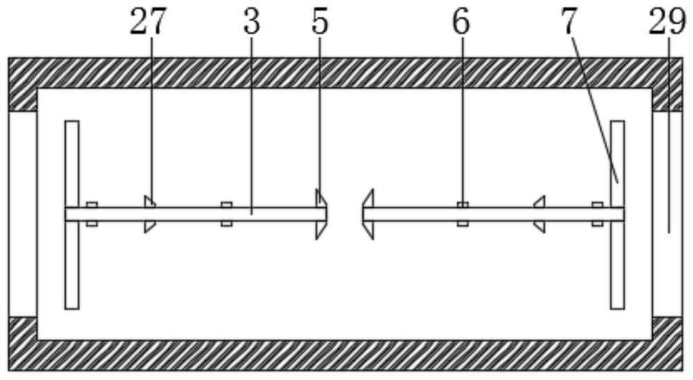
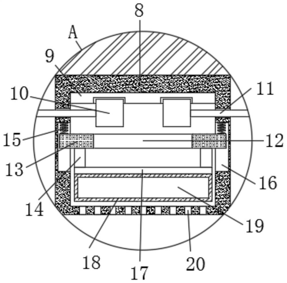
The invention discloses hot fluid pipeline full-ceramic electric heating body heating control device. The device comprises a shell, the top of the shell is horizontally and fixedly connected with a pair of mounting rods through fixing parts, and heat dissipation openings are formed at the ends, away from each other, close to the two mounting rods correspondingly; and the top of the shell is provided with a driving part used for driving the two mounting rods to rotate, the ends, close to the heat dissipation openings, of the mounting rods rods are fixedly sleeved with heat dissipation blades, the top of the shell is fixedly connected with a temperature control switch, and the temperature control switch comprises an installation shell. According to the device, low-temperature evaporation liquid in an air bag is gasified through heat generated when an electric appliance element works, so that the air bag expands to push a copper rod to ascend, a power source, the temperature control switch and a motor form a complete current loop, the motor drives the two heat dissipation blades to rotate, exchange of air in the shell and external air is accelerated, therefore, high-temperature gas in the shell is discharged, and electronic elements in the shell are protected.

Description

technical field [0001] The invention relates to the technical field of thermal fluid pipeline heating, in particular to a heating control device for a thermal fluid pipeline all-ceramic electric heater. Background technique [0002] In hot fluid pipelines such as injection molding machine hot fluid pipelines, heating the fluid can make the fluid flow fully and have good uniformity, thereby ensuring the goodness of the product. [0003] Usually, the control devices used to heat the fluid in the pipeline are installed in an operation cabinet, so that the user can control the temperature of the heating pipeline by setting the program. When the heating device is working, the electrical components in the operation cabinet also work. A lot of heat will be generated during use, but the heat dissipation of existing operation cabinets usually requires the user to open the door to ventilate when he feels the heat. Due to the work intensity of the user, and the neglect of ventilation ...

Claims


Application Information

Patent Timeline
Patent Type & Authority Applications(China)
IPC IPC(8): B29C45/27B29C45/73B29C45/78B29C45/17B08B5/02
CPCB29C45/2737B29C45/78B29C45/1753B08B5/02B29C2045/2743
Inventor 岳丹
Owner ZHICHENG JIN TECH
Why Eureka
Eureka Blog
Learn More