Reusable fixing structure
A technology for fixing structures and objects, applied in the direction of light guides, optics, instruments, etc., can solve the problems of high material cost, long time consumption, damage and waste of raw materials, etc., and achieve the effect of saving material cost, saving materials, and simple fixing steps
- Summary
- Abstract
- Description
- Claims
- Application Information
AI Technical Summary
Problems solved by technology
Method used
Image

Examples
Embodiment 1
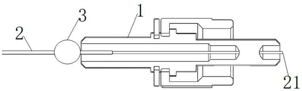
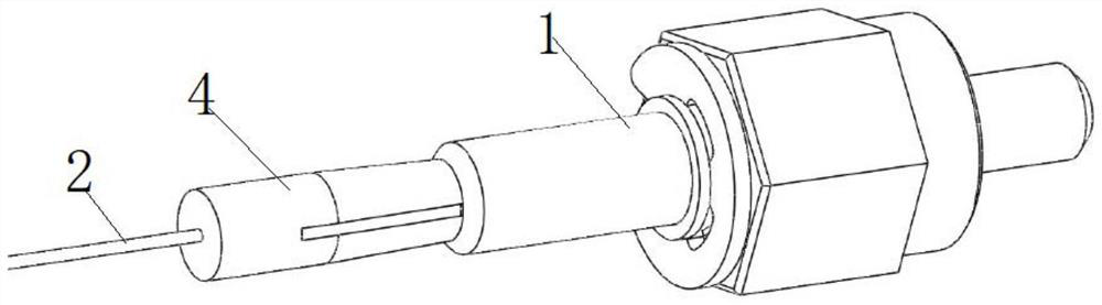
[0056] This embodiment provides a reusable fixed structure, such as Figure 3 to Figure 6 As shown, it includes a fixed body 4 made of a material with a high coefficient of friction. The fixed body 4 includes an insertion portion 41 and a balance portion 42 disposed on one end surface 21 of the insertion portion 41 .
[0057] see Figure 5 and Figure 6 , the balance part 42 is provided with an insertion hole 43, and the insertion hole 43 extends along the length direction of the fixed body 4; the insertion part 41 is provided with a groove 44 communicating with the insertion hole 43, and the two sides of the groove 44 are connected to the The outside world is connected, that is, the groove 44 separates the insertion part 41 into upper and lower parts. The axis of the insertion hole 43 coincides with the axis of the groove 44, and the object to be fixed passes through the groove 44 and the insertion hole 43. When the insertion part 41 squeezes the object to be fixed, the ax...
Embodiment 2
[0065] This embodiment provides a reusable fixed structure, such as Figure 7 to Figure 10 As shown, the difference between it and the fixing structure in Embodiment 1 is that the outer contours of the socket part 41 and the balance part 42 are both cylindrical, and the outer wall of the fixed body 4 on the side of the groove 44 is provided with a The wedge groove 45 extending from the insertion part 41 has a bottom of an arc surface, and the depth of the wedge groove 45 gradually becomes shallower from the balance part 42 to the insertion part 41 . The end of the wedge groove 45 extends to the middle of the insertion portion 41 and is located above the groove 44 , so that the insertion portion 41 is pressed down through the groove 44 after the wedge is inserted into the wedge groove 45 .
[0066] see Figure 10 , the groove wall of the groove 44 on the side where the wedge groove 45 is located is recessed outwards to form an arc wall 46 , and the arc wall 46 coincides with t...
Embodiment 3
[0073] This embodiment provides a reusable fixed structure, such as Figure 11 to Figure 14 As shown, the difference between it and the fixing structure provided in Embodiment 1 and Embodiment 2 is that: the groove 44 is arranged on the balance part 42, and the groove 44 separates the balance part 42 into upper and lower parts; the insertion hole 43 is arranged on on the socket part 41.
[0074] see Figure 13 and Figure 14 The outer contours of the balance part 42 and the socket part 41 are cylindrical, and the diameter of the balance part 42 is greater than the diameter of the socket part 41; one side of the groove 44 is recessed outwards to form an arc wall 46, and the arc The wall 46 coincides with the extension surface of the hole wall of the insertion hole 43 . The outer diameter of the insertion part 41 is slightly smaller than the inner diameter of the insertion hole, so as to ensure that the insertion part 41 can be inserted into the insertion hole.
[0075] When...
PUM
 Abstract
Description
Claims
Application Information
 - R&D
- Intellectual Property
- Life Sciences
- Materials
- Tech Scout
- Unparalleled Data Quality
- Higher Quality Content
- 60% Fewer Hallucinations
Browse by: Latest US Patents, China's latest patents, Technical Efficacy Thesaurus, Application Domain, Technology Topic, Popular Technical Reports.
© 2025 PatSnap. All rights reserved.Legal|Privacy policy|Modern Slavery Act Transparency Statement|Sitemap|About US| Contact US: help@patsnap.com