
Metal particle detection sensor based on high-frequency high-gradient magnetic field and detection method thereof

A high-gradient magnetic field, detection sensor technology, applied in the size/direction of the magnetic field, magnetic gradient measurement, magnetic field measurement using electromagnetic devices, etc., to achieve the effect of improving detection capability, enhancing detection capability, and compact structure

Active Publication Date: 2021-06-01
CHONGQING UNIV OF POSTS & TELECOMM
View PDF10 Cites 3 Cited by
  • Summary
  • Abstract
  • Description
  • Claims
  • Application Information

AI Technical Summary

Problems solved by technology

However, the traditional electromagnetic wear particle detection sensor is often limited by the frequency and strength of the magnetic field, and most of the minimum detection accuracy is maintained at 60-120 microns, making it difficult for the sensor to complete the detection of tiny metal abrasive particles of different materials

Method used


Image

  • Metal particle detection sensor based on high-frequency high-gradient magnetic field and detection method thereof
  • Metal particle detection sensor based on high-frequency high-gradient magnetic field and detection method thereof
  • Metal particle detection sensor based on high-frequency high-gradient magnetic field and detection method thereof

Examples


Embodiment 1

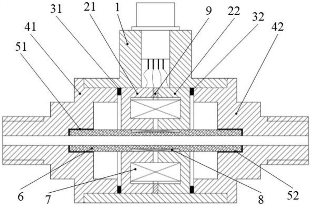
[0026] This embodiment further describes the above sensors.

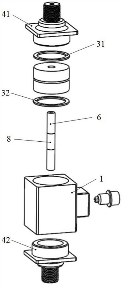
[0027] Further, a first sealing rubber ring 51 and a second sealing rubber ring 52 are respectively provided at the joints of the first pipe joint 41 , the second pipe joint 42 and the oil pipe 6 .

[0028] Further, a first rubber gasket 31 and a second rubber gasket 32 ​​are provided at the joints between the first pipe joint 41 and the second pipe joint 42 and the first pot-shaped magnetic pole 21 and the second pot-shaped magnetic pole 22 respectively.

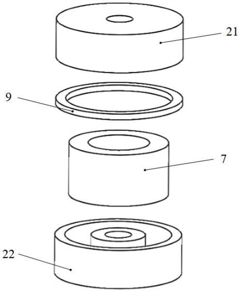
[0029] As in 3, the first pot-shaped magnetic pole 21 and the second pot-shaped magnetic pole 22 are circular groove structures, and the center position is a through hole. The circular groove structures of the first can-shaped magnetic pole 21 and the second can-shaped magnetic pole 22 are arranged symmetrically and facing each other.

[0030] The material of the first can-shaped magnetic pole 21 and the second can-shaped magnetic pole 22 is ferrite, and there i...

Embodiment 2

[0033] This embodiment provides a detection method of a metal particle detection sensor based on a high-frequency high-gradient magnetic field, including the metal particle detection sensor based on a high-frequency high-gradient magnetic field described in Embodiment 1, specifically including the following steps:

[0034] S1. The internal excitation coil 7 of the metal abrasive particle detection sensor passes high-frequency alternating current in the range of 10kHz-5MHz as excitation;

[0035] S2. When metal abrasive grains inside the oil pipe pass through the high-frequency and high-gradient magnetic field, the metal abrasive grain detection sensor can reflect the characteristics of the abrasive grains through changes in the induced voltage of the detection coil 8 .

[0036] When the metal abrasive particles pass through the sensor, the abrasive particles will affect the change of the magnetic flux, and then affect the change of the induced voltage. The winding direction of ...


PUM


Abstract

The invention relates to the field of mechanical equipment condition monitoring, in particular to a metal particle detection sensor based on a high-frequency high-gradient magnetic field and a detection method thereof. The sensor comprises a sensor shell assembly, a magnetic field loop assembly and an oil pipe detection assembly. The sensor shell assembly comprises a shell, a first pipe connector and a second pipe connector, a through hole is formed in the side face of the shell, and the first pipe connector and the second pipe connector are arranged at through hole openings in the two sides of the shell respectively. The oil pipe detection assembly is located in the center of the shell and comprises an induction coil and an oil pipe, the oil pipe is located in an inner cavity of the sensor, the two ends of the oil pipe are connected with the first pipe connector and the second pipe connector in an embedded mode respectively, a groove is formed in the outer side of the pipe wall of the oil pipe, and the induction coil is wound in the oil pipe groove. The magnetic field loop assembly is located on the outer surface of the induction coil and comprises a first tank-shaped magnetic pole, a second tank-shaped magnetic pole and an excitation coil.

Description

technical field [0001] The invention relates to the field of mechanical equipment status monitoring, in particular to a metal particle detection sensor and a detection method based on a high-frequency high-gradient magnetic field. Background technique [0002] As an integral part of large-scale mechanical equipment, the lubrication system can reduce friction, cool, prevent corrosion and seal, and also carry important information about mechanical wear. Among them, wear particles are the carrier of wear state information, and their detection can reflect the health status of machinery, so as to evaluate the working conditions of equipment parts and even predict the occurrence of mechanical failures. [0003] In the lubrication system, the size, material and shape characteristics of the wear particles produced by different wear modes between different friction pairs are also different. At present, the on-line oil wear sensor mainly adopts methods such as image type and electrom...

Claims


Application Information

Patent Timeline
Patent Type & Authority Applications(China)
IPC IPC(8): G01N15/02G01R33/022
CPCG01N15/02G01R33/022
Inventor 冯松杨磊磊谭军谢海琼罗久飞
Owner CHONGQING UNIV OF POSTS & TELECOMM
Learn More