
Super high-rise core tube joint bar retaining device and system and joint bar pre-embedding construction method

A core tube and super high-rise technology, applied in the direction of structural elements, building components, building reinforcements, etc., can solve the problems of poor construction effect and large loss of inserted ribs, so as to facilitate demoulding and disassembly operations, improve construction efficiency, and facilitate The effect of demoulding

Inactive Publication Date: 2021-06-01
CHINA MCC17 GRP
View PDF0 Cites 0 Cited by
  • Summary
  • Abstract
  • Description
  • Claims
  • Application Information

AI Technical Summary

Problems solved by technology

[0008] The purpose of the present invention is to overcome the problems of large loss and poor construction effect in conventional formwork drilling in the prior art, and to provide a super-high-rise core tube inserting bar retention device and system and a pre-embedded construction method for inserting bars. The present invention The indwelling device can be used in conjunction with various formwork, and it is easy to install and disassemble; using the indwelling device for construction can effectively improve the construction effect of pre-embedded ribs on the floor deck, ensure the position of pre-embedded ribs, reduce the loss of formwork, and further Save construction cost

Method used


Image

  • Super high-rise core tube joint bar retaining device and system and joint bar pre-embedding construction method
  • Super high-rise core tube joint bar retaining device and system and joint bar pre-embedding construction method
  • Super high-rise core tube joint bar retaining device and system and joint bar pre-embedding construction method

Examples


Embodiment 1

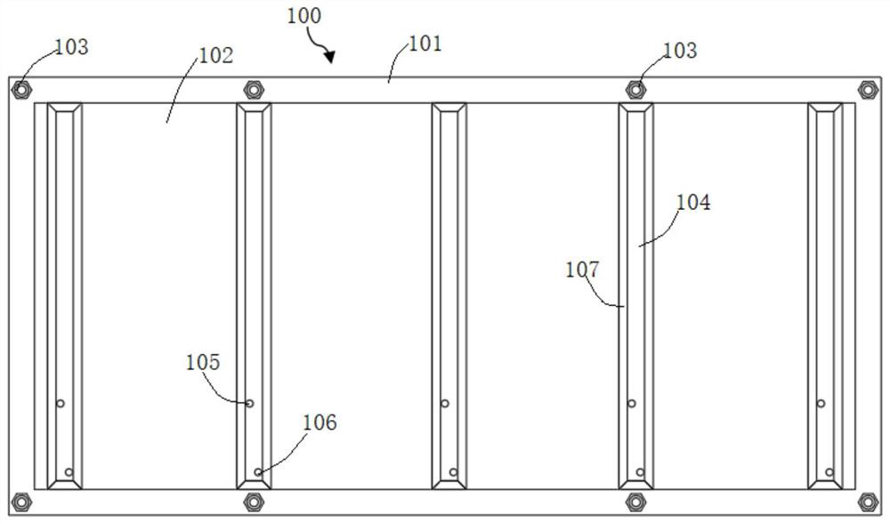
[0038] Such as figure 1 and figure 2 As shown, the indwelling device for super high-rise core tube inserting ribs in this embodiment, the indwelling device 100 includes a wing plate 101, a web 102 and a rib groove plate 107, the wing plate 101 forms a peripheral frame, and multiple sets of webs 102 are evenly spaced and parallel It is arranged inside the frame of the wing plate 101, and a grooved plate 107 is arranged between two adjacent groups of webs 102. The grooved plate 107 extends and protrudes toward the side of the web 102, and there is an opening in the grooved plate 107. The rib slot 104 and the upper bottom of the protruding bottom wall of the rib slot plate 107 are provided with an upper rib hole 105 and a lower rib hole 106 communicating with the rib slot 104 .

[0039] Specifically, in this embodiment, the wing plate 101 is a frame made of strip steel plates, and the web 102 is made of rectangular steel plates. The thickness of the wing plate 101 and the web pla...

Embodiment 2

[0044] The super-high-rise core tube inserting bar retention device of this embodiment is basically the same as that of Embodiment 1. Furthermore, in this embodiment, the end of the wire cap 108 away from the direction of the wing plate 101 is a closed structure, and the end of the wire cap 108 close to the direction of the wing plate 101 is a closed structure. There is no gap connection between one end and the wing plate 101 . More specifically, the screw cap 108 should be configured as a cylindrical or regular polygonal sleeve structure, and the sleeve is provided with a threaded hole matching with the bolt 103, and the sleeve can be integrated with the wing plate 101 to ensure a gap-free connection. The end of the sleeve away from the direction of the wing plate 101 is a closed structure to ensure that the pouring quality will not be affected during the pouring process and to facilitate subsequent demoulding and disassembly operations.

[0045] In this embodiment, the rib g...

Embodiment 3

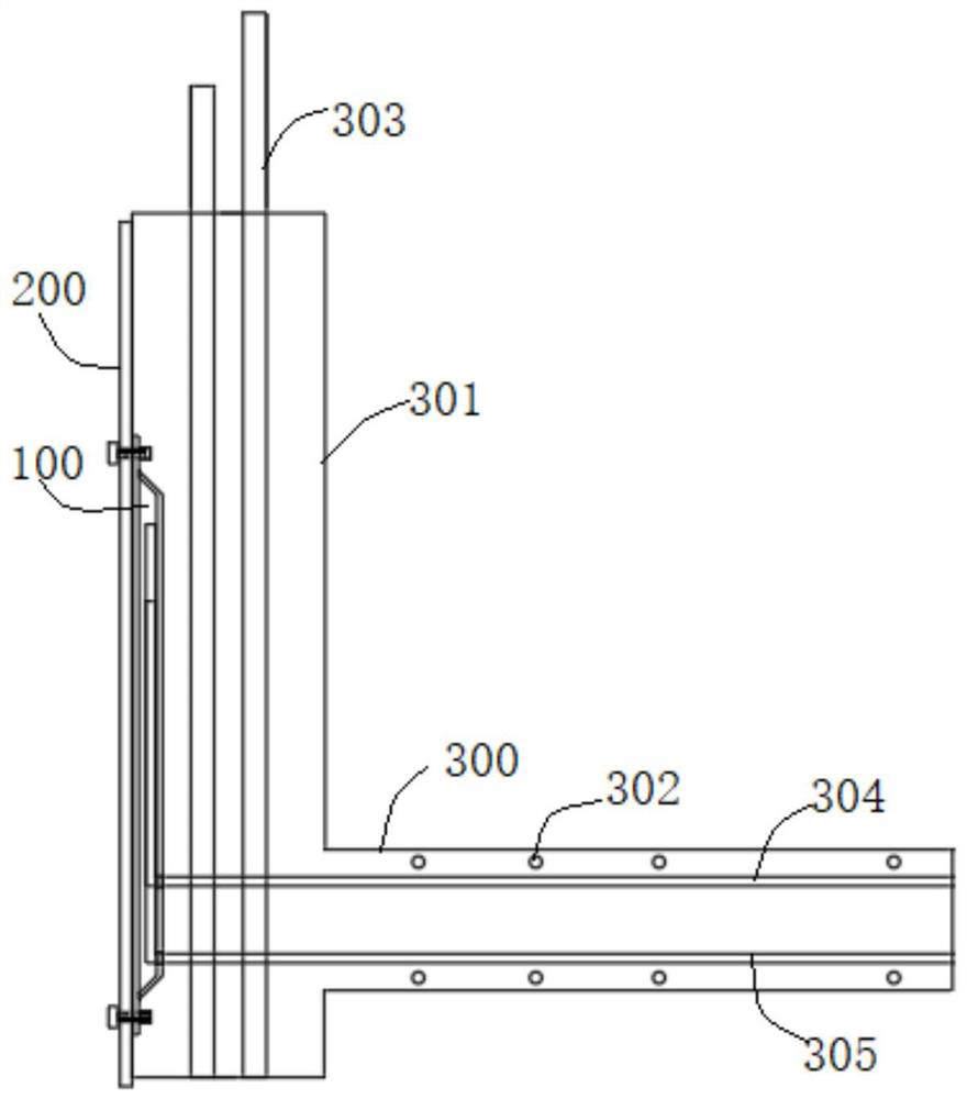
[0047] The super-high-rise core tube insertion bar indwelling system of this embodiment includes a template 200 and the indwelling device 100 in the above-mentioned embodiment, that is, the indwelling device 100 is provided with installation holes and thread caps 108, and the template 200 is correspondingly provided with installation holes and bolts. 103 cooperates with the silk cap 108 to securely connect the template 200 and the indwelling device 100. The side of the indwelling device 100 facing away from the template 200 is provided with an outwardly protruding groove plate 107, and there is a rib facing the template 200 in the rib groove plate 107. The rib insertion groove 104 of the opening, the outwardly protruding bottom wall of the rib groove plate 107 is provided with an upper rib hole 105 and a lower rib hole 106 communicating with the rib insertion groove 104, and the specific structure of the indwelling device 100 will not be repeated. Specific as image 3 Shown is...


PUM


Abstract

The invention discloses a super high-rise core tube joint bar retaining device and system and a joint bar pre-embedding construction method, and belongs to the field of core tube structure construction. The retaining device comprises wing plates, web plates and bar groove plates, wherein a plurality of sets of web plates are uniformly arranged in a wing plate frame in parallel at intervals, the bar groove plates are arranged between every two adjacent sets of web plates, the bar groove plates protrude towards one sides of the web plates, joint bar grooves are formed in the bar groove plates, and upper bar holes and lower bar holes which communicate with the joint bar grooves are formed in the bar groove plates. According to the super high-rise core tube joint bar retaining device and system and the joint bar pre-embedding construction method, the problems that the loss of retaining joint bars of conventional formwork drilling is large, and the construction effect is poor are solved, the retaining device can be suitable for being matched with various formworks for use, and mounting and dismounting are convenient; and the retaining device is used for construction, the construction effect of pre-embedding the joint bars of a floor support plate can be effectively improved, the position of the pre-embedded joint bars is guaranteed, and the formwork loss is reduced.

Description

technical field [0001] The invention relates to the technical field of construction of a steel frame-reinforced concrete core tube structure, and more specifically, relates to a super high-rise core tube inserting bar retention device and system and a bar inserting pre-embedded construction method. Background technique [0002] With the development of high-rise buildings, the steel frame-reinforced concrete core tube structure has been widely used in super high-rise buildings due to its high bearing capacity, light weight, good seismic performance, high degree of industrialization, and short construction period. [0003] In the steel frame-reinforced concrete core tube structure system, the core tube is generally adopted in the industry ahead of the outer steel frame construction technology. After the outer frame steel columns and steel beams are installed, the floor deck construction will be carried out. Pre-embedding is carried out during the construction of the reinforced...

Claims


Application Information

Patent Timeline
IPC IPC(8): E04C5/16E04B1/41
CPCE04B1/41E04C5/168
Inventor 乔小明尹万云金仁才钱元弟
Owner CHINA MCC17 GRP
Learn More