
GaAs E/D process low-power-consumption phase inverter circuit

An inverter and low power consumption technology, applied in logic circuits, electrical components, pulse technology, etc., can solve the problems of increasing inverter power consumption, large power supply voltage deviation, and large quiescent current, so as to reduce layout area, The effect of simplifying the circuit structure and reducing static power consumption

Inactive Publication Date: 2021-05-28
HEFEI IC VALLEY MICROELECTRONICS CO LTD
View PDF4 Cites 0 Cited by
  • Summary
  • Abstract
  • Description
  • Claims
  • Application Information

AI Technical Summary

Problems solved by technology

[0005] However, prior art ( figure 1 ) has strict requirements on high and low levels. If the voltage value deviates slightly, the inverter will not work properly. The number of reversed phases is large, the static current is large, and the power consumption of the inverter will be increased.
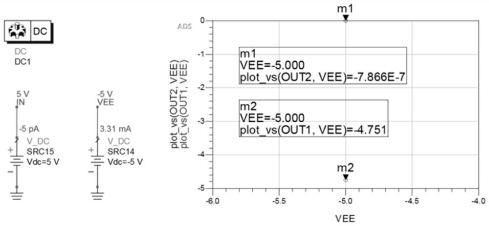
[0006] figure 2 However, it is the simulation result of the inverter in the prior art, it can be seen that the quiescent current is relatively large, and the deviation between the low-level output and the power supply voltage is slightly larger

Method used


Image

  • GaAs E/D process low-power-consumption phase inverter circuit
  • GaAs E/D process low-power-consumption phase inverter circuit
  • GaAs E/D process low-power-consumption phase inverter circuit

Examples


Embodiment

[0020] see Figure 1 to Figure 3 , the present invention provides a technical solution:

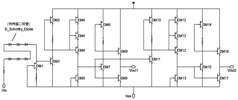
[0021] The invention proposes a new low power consumption inverter circuit. In the existing inverter, the drain of the potential shift output point D tube (DM1) is connected to the gate of the E tube (EM3), and the conduction of the E tube (EM4) is controlled by controlling the switch of the E tube (EM3) or off, the output can control the E tube (EM7 and EM9) to turn on or off the required high and low level -4 / -5V, and an output signal of 0V or -5V is obtained through the drain output of the E tube (EM9); the E tube ( After the gate of EM7), continue to connect two stages of inversion to get a complementary output signal -4.75V or 0V, where the gate and source of the D tubes (DM2, DM6, DM10, DM14) are connected as a constant current source.

[0022] Further, through the potential shift circuit, the TTL logic control level is converted into -4 / -5V high and low levels that can meet the o...


PUM


Abstract

According to the GaAs E / D process low-power-consumption phase inverter circuit, Vin is a TTL control logic level, voltage reduction is carried out through six diodes, and a TTL logic control signal is converted into -4 / -5V of high and low levels capable of meeting the requirement for opening or closing a GaAs E tube. A drain electrode of a D tube (DM1) at a potential translation tail end is connected with a grid electrode of an E tube (EM3) in a first-stage phase, a first-stage output (Vout1) is connected with a drain electrode of an E tube (EM4) of which a grid electrode is connected with a source electrode, is connected with a grid electrode of an E tube (EM6) in a second-stage phase, and serves as a second-stage output (Vout2) through a drain electrode of the E tube (EM6). And finally, a pair of complementary differential signals is obtained, and the output high and low levels are respectively 0 / -4.95 V, so that the requirement of turning on or turning off a GaAs switch can be met. Grid electrodes and source electrodes of the D tube (DM2) and the D tube (DM5) are mutually connected to form a constant current source, and static power consumption is reduced through a stacking structure and a series resistor mode.

Description

technical field [0001] The invention relates to the technical field of inverters, in particular to a GaAs E / D process low-power inverter circuit. Background technique [0002] figure 1 It is a structural schematic diagram of an inverter circuit in the prior art. In the inverter of the prior art, the TTL logic control level is converted into -4 / -5V which can meet the high and low level requirements of the GaAs E tube to be turned on or off through the potential shift circuit, and then converted into The high and low levels are -4.75 / 0V, and then converted into an inverse complementary voltage of 0 / -4.75V through two stages of inversion. The entire inverter converts the TTL logic control level into a pair of complementary differential signals through four stages of inversion. [0003] The drain of the potential shift output point D tube (DM1) is connected to the gate of the E tube (EM3). By controlling the switch of the E tube (EM3) to control the conduction or shutdown of ...

Claims


Application Information

Patent Timeline
Patent Type & Authority Applications(China)
IPC IPC(8): H03K19/094
CPCH03K19/094
Inventor 梅连峰黄军恒
Owner HEFEI IC VALLEY MICROELECTRONICS CO LTD
Learn More