
Broadband aperture waveguide structure dual circularly polarized antenna based on 3D printing technology

A 3D printing, waveguide structure technology, applied in the directions of antenna, waveguide horn, radiating element structure, etc., can solve the problems of difficult to achieve flexible rotation switching, single polarization mode, narrow axial ratio bandwidth, etc., to achieve light weight, gain Stable, pattern stabilization effect

Active Publication Date: 2022-03-29
SOUTH CHINA UNIV OF TECH
View PDF9 Cites 0 Cited by
  • Summary
  • Abstract
  • Description
  • Claims
  • Application Information

AI Technical Summary

Problems solved by technology

[0010] The present invention provides a broadband aperture waveguide structure dual circularly polarized antenna based on 3D printing technology to solve the traditional aperture waveguide structure circularly polarized antenna in the prior art with narrow axial ratio bandwidth, heavy weight, difficult processing and single polarization mode. Realize flexible switching of rotation direction and other issues

Method used


Image

  • Broadband aperture waveguide structure dual circularly polarized antenna based on 3D printing technology
  • Broadband aperture waveguide structure dual circularly polarized antenna based on 3D printing technology
  • Broadband aperture waveguide structure dual circularly polarized antenna based on 3D printing technology

Examples


Embodiment Construction

[0030] In order to better understand the present invention, the content of the present invention is further illustrated below in conjunction with the examples, but the content of the present invention is not limited to the following examples.

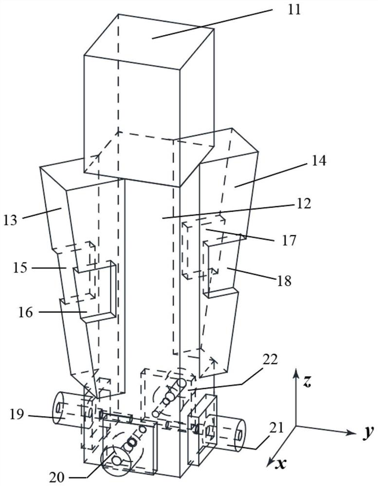
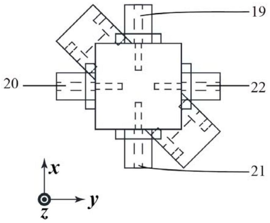
[0031] Such as figure 1 As shown, the antenna includes a rectangular dielectric block 11, a rectangular waveguide 12, a first wedge structure 13, a second wedge structure 14, a first differential port and a second differential port. The rectangular dielectric block 11 , the rectangular waveguide 12 , the first wedge-shaped structure 13 and the second wedge-shaped structure 14 are made of 3D printing medium material, and the entire structure is integrally formed. The outer surfaces of the rectangular waveguide 12 , the first wedge-shaped structure 13 and the second wedge-shaped structure 14 are covered with a thin layer of metal copper by electroplating. In this embodiment, the relative permittivity of the dielectric material is 2.9, an...


PUM


Abstract

The dual-circularly polarized antenna with broadband aperture waveguide structure based on 3D printing technology provided by the present invention includes a rectangular dielectric block, a rectangular waveguide, a first wedge-shaped structure and a second wedge-shaped structure, the rectangular dielectric block is located above the rectangular waveguide; the first wedge-shaped structure and the second wedge-shaped structure are respectively located at two diagonal positions of the rectangular waveguide and are symmetrical with respect to the central axis of the antenna; the first wedge-shaped structure and the second wedge-shaped structure are respectively provided with a pair of opposite rectangular concaves for improving the axial ratio bandwidth Groove; the distance from the bottom surface of the rectangular waveguide to a quarter of the waveguide wavelength is provided with a first differential port and a second differential port for feeding, and the two differential ports are arranged orthogonally. The antenna is integrally formed by 3D printing medium material, and a metal layer is plated on the surfaces of the rectangular waveguide, the first wedge-shaped structure and the second wedge-shaped structure. The invention has simple structure and convenient processing, and has the advantages of wide axial ratio bandwidth, stable gain, stable pattern, and flexible switching of circular polarization rotation direction.

Description

technical field [0001] The invention relates to the technical field of antennas, in particular to a broadband aperture waveguide structure dual circularly polarized antenna based on 3D printing technology. Background technique [0002] 3D printing technology is an emerging technology for rapid prototyping of three-dimensional structures with additive methods as the main means. Compared with traditional three-dimensional processing technology, such as: CNC, injection molding, etc., 3D printing technology has a series of advantages such as simple manufacturing procedures, short processing cycle, efficient forming of complex structures, and high material utilization rate. At present, this technology has been widely used in various fields, such as education, medical care, aerospace, architecture, engineering, etc. At the same time, 3D printing technology has also received a lot of attention in the field of antenna research. In recent years, many antenna designs based on this te...

Claims


Application Information

Patent Timeline
Patent Type & Authority Patents(China)
IPC IPC(8): H01Q1/36H01Q13/02B33Y80/00
CPCH01Q1/36H01Q13/0241B33Y80/00
Inventor 马自龙张楚唯
Owner SOUTH CHINA UNIV OF TECH
Learn More