Force measuring equipment of digital caliper based on piezoelectric material
A technology of digital calipers and piezoelectric materials, applied in the field of piezoelectric materials, can solve problems such as changes in triggering pressure
- Summary
- Abstract
- Description
- Claims
- Application Information
AI Technical Summary
Problems solved by technology
Method used
Image
Examples
Embodiment 1
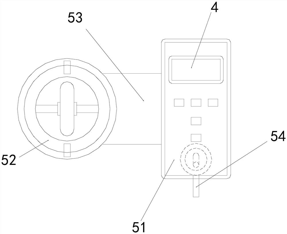
[0025] as attached figure 1 to attach Figure 4 As shown, the present invention provides a force-measuring device based on a piezoelectric material digital caliper, a placement plate 1, a control machine 2, a guide seat 3, a display panel 4, and a force-measuring device 5, and the left side of the placement plate 1 is welded Fixed on the lower end of the right side of the control machine 2, the upper end of the control machine 2 is fixed to the lower end of the guide seat 3 by screws, the outer wall of the display panel 4 is nested and fixed on the upper end of the inner wall of the front end of the force measuring device 5, and the left side of the force measuring device 5 The outer wall is nested and engaged with the inner wall on the right side of the guide seat 3;
[0026] The force-measuring device 5 is composed of a digital display 51, a lifter 52, a connecting plate 53, and a force detector 54. The left side of the digital display 51 is connected to the right side of t...
Embodiment 2
[0031] as attached Figure 5 to attach Figure 7 As shown: the lifter 52 is composed of a positioning ring c1, a snap ring c2, a connecting rod c3, a positioning block c4, and a magnetizer c5. The outer wall of the positioning ring c1 is nested and engaged with the inner wall of the guide seat 3. The snap ring The outer wall of c2 is interferingly fixed on the inner wall of the positioning ring c1, the outer wall at both ends of the connecting rod c3 is embedded and fixed between the snap ring c2, one end of the positioning block c4 is welded and fixed on the upper and lower surfaces of the snap ring c2, and the magnetizer The inner wall of c5 is nested and engaged with the outer wall of the center of the connecting rod c3. There are two positioning rings c1, which are relatively arranged at the upper and lower ends of the surface of the snap ring c2. The snap rings c2 at the upper and lower ends are located at the magnetizer c5 It is a straight line, determined by the position...
PUM
 Abstract
Description
Claims
Application Information
 - R&D Engineer
- R&D Manager
- IP Professional
- Industry Leading Data Capabilities
- Powerful AI technology
- Patent DNA Extraction
Browse by: Latest US Patents, China's latest patents, Technical Efficacy Thesaurus, Application Domain, Technology Topic, Popular Technical Reports.
© 2024 PatSnap. All rights reserved.Legal|Privacy policy|Modern Slavery Act Transparency Statement|Sitemap|About US| Contact US: help@patsnap.com


