Gas ejector

A technology of ejector and gas, which is applied in jet pumps, machines/engines, non-volume pumps, etc., to achieve the effects of improving ejector efficiency, improving versatility, and facilitating installation

Pending Publication Date: 2021-05-28
郭孝国
View PDF0 Cites 3 Cited by
  • Summary
  • Abstract
  • Description
  • Claims
  • Application Information

AI Technical Summary

Problems solved by technology

[0004] The purpose of the present invention is to provide a gas ejector for the existing ejector to change the area ratio of the flow area of ​​the t

Method used


Image

  • Gas ejector
  • Gas ejector
  • Gas ejector

Examples


Embodiment Construction

[0030] The present invention will be described in further detail below in conjunction with the accompanying drawings. Wherein the same components are denoted by the same reference numerals.

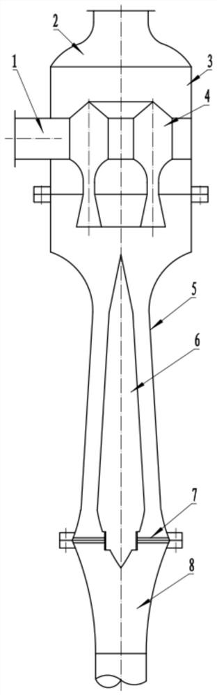
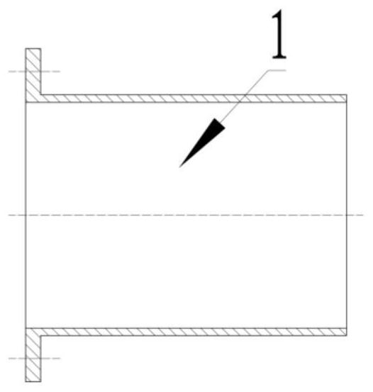
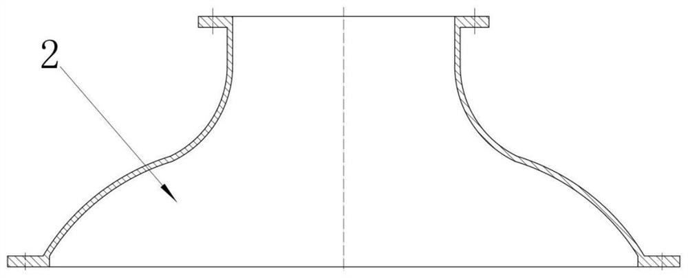
[0031] A gas ejector such as figure 1 As shown, it includes a suction chamber 3 , a diffuser outer cylinder 5 , an exhaust tailpipe 8 , an annular nozzle 4 and a diffuser cone 6 . The suction chamber 3, the diffuser outer cylinder 5, and the exhaust tail pipe 8 are sealed and communicated in sequence, and each pipe is arranged coaxially. The annular nozzle 4 is arranged in the suction chamber 3 and is coaxial with the suction chamber 3, combined with figure 2 with Figure 5 As shown, the annular nozzle 4 is communicated with the jet inlet pipe 1 extending out of the suction chamber 3, and the end of the annular nozzle 4 facing the exhaust tailpipe 8 is provided with an annular nozzle coaxial with its body, and part of the nozzles of the annular nozzle 4 Stretch into the diffuser oute...


PUM


Abstract

In order to solve the problem that the structures of a nozzle and a throat section need to be redesigned and manufactured when the area ratio of an existing ejector is changed, the invention provides a gas ejector which comprises a suction chamber, a diffusion outer cylinder and an exhaust tail pipe which are sequentially communicated and coaxial, wherein the diffusion outer cylinder comprises a mixing part, a contraction part, a throat part and an expansion part; and the suction chamber is fixedly provided with an annular spray pipe, a diffusion cone is fixedly arranged in the diffusion outer cylinder and comprises a conical cone section I, a circular truncated cone-shaped cone section II and a circular truncated cone-shaped cone section III, the conical section I, the conical section II and the conical section III are sequentially and coaxially connected, the diffusion cone is coaxial with the diffusion outer cylinder, the bottom of the conical section I is connected with the upper bottom of the conical section II, the bottom of the conical section II is connected with the lower bottom of the conical section III, the lower bottom of the conical section II is connected with the lower bottom of the third conical section, the conical section I is located in the contraction part, the conical section II is located in the throat part, the conical section III is located in the expansion part, and the outer molded surface of the conical section II is parallel to the inner wall of the throat part. The gas ejector is compact in structure, facilitates the size with higher throat sections, simple in structure, easy to machine and manufacture and convenient to mount.

Description

technical field [0001] The invention relates to the field of vacuum refrigeration, in particular to a gas ejector. Background technique [0002] Injectors are widely used in industrial production departments, machinery manufacturing, light industry, chemical industry, textile and other industries, no matter in operation or economic and technical comparison, they are relatively convenient, applicable, and economical and reasonable. In the case of refrigeration and vacuuming, it can replace compressors, mechanical vacuum pumps, etc. In addition, because it does not need vulnerable spare parts, it is reliable in operation and has a long service life. Especially in some occasions, air and steam are used as the medium, the structure is simple, the cost is low, and the operation, use and maintenance are relatively simple, especially in some industrial production. The comprehensive utilization of waste heat and waste gas has greater economic significance. [0003] The ejectors cu...

Claims


Application Information

Patent Timeline
IPC IPC(8): F04F5/16F04F5/44F04F5/46
CPCF04F5/16F04F5/44F04F5/46F04F5/465F04F5/466
Inventor 郭孝国
Owner 郭孝国
Why Eureka
Try Eureka