
Particle inertial-capacitance damping device

A technology of damping devices and particles, which is applied in the direction of building types, buildings, building components, etc., can solve the problems of difficult vibration conditions of particle dampers, reduce the vibration conditions of damping particles, and do not have their own energy consumption capacity, so as to achieve maintenance costs Low cost, reduced vibration conditions, and simple structure

Active Publication Date: 2021-05-28
BEIJING UNIV OF TECH
View PDF17 Cites 1 Cited by
  • Summary
  • Abstract
  • Description
  • Claims
  • Application Information

AI Technical Summary

Problems solved by technology

[0004] In order to solve the problems that the traditional inerter device does not have its own energy consumption capacity, the vibration starting condition of the traditional particle damper is difficult, and the energy consumption capacity is difficult to exert during small earthquakes, etc., the present invention proposes an inertial energy-absorbing device, and through the inerter device Accelerate the damping particles to further absorb the kinetic energy of the controlled structure; and reduce the vibration conditions of the damping particles, and then pass through the particle inertial damping device that damps the particles to collide and consume frictional energy

Method used


Image

  • Particle inertial-capacitance damping device
  • Particle inertial-capacitance damping device
  • Particle inertial-capacitance damping device

Examples


Embodiment 1

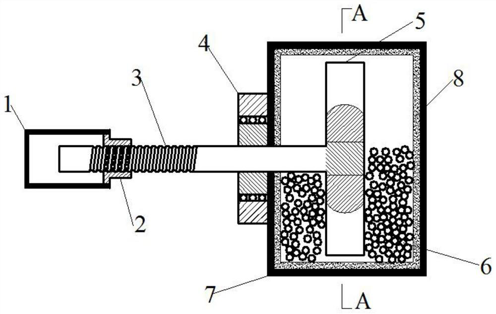
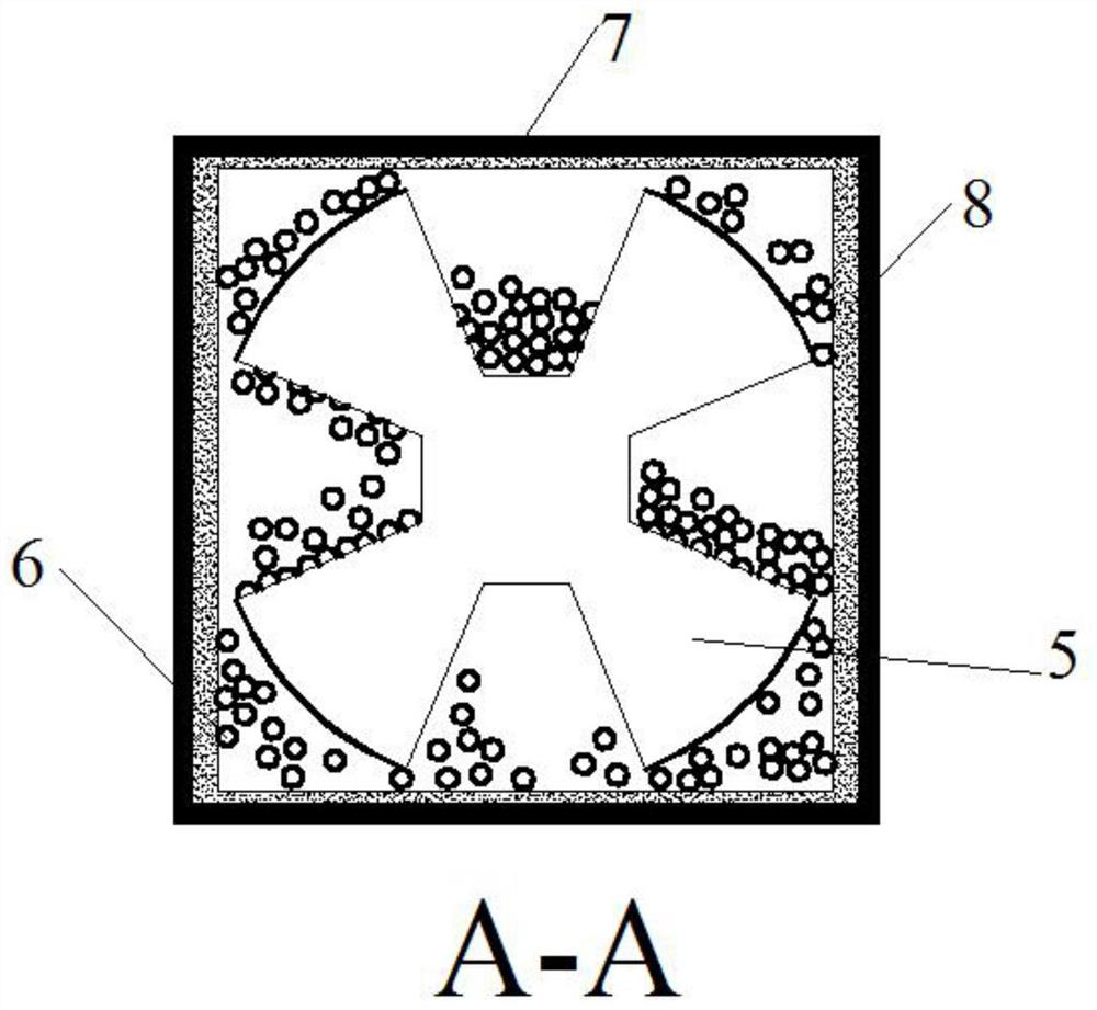
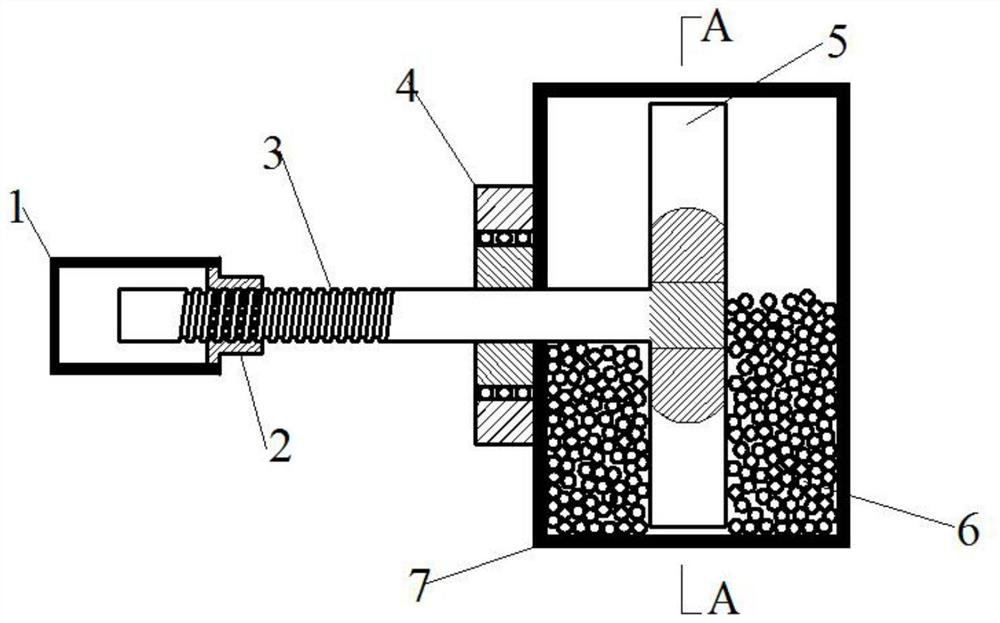
[0020] like figure 1 , figure 2 , image 3 and Figure 4 Shown is a particle inertial capacity damping device, which is mainly used between bridge piers and beams to play a role in shock absorption (vibration). It includes a metal casing one (1), a nut (2), a ball screw (3), a bearing (4), a flywheel (5), particles (6), a metal casing two (7) and an energy dissipation layer (8). Metal case one (1) has a size of 320mm×150mm×110mm and a thickness of 12mm. Metal case two (7) has a size of 320mm×320mm×320mm and a thickness of 12mm. The ball screw (3) has a diameter of 60mm and a length according to The maximum displacement of the controlled structure is determined. The flywheel (5) has a diameter of 280mm and a thickness of 150mm. The grooves on the flywheel (5) have different sizes according to the shock absorption requirements. The diameter of the particles (6) is 10mm. According to the shock absorption requirements, the metal casing two (7) The filling rate of the inner pa...

Embodiment 2

[0023] like figure 1 , figure 2 , image 3 and Figure 4Shown is a particle inertial capacity damping device, which is mainly used in the interstory of high-rise buildings or in the buffer layer of blasting structures to play the role of shock absorption (vibration). It includes a metal casing one (1), a nut (2), a ball screw (3), a bearing (4), a flywheel (5), particles (6), a metal casing two (7) and an energy dissipation layer (8). Metal case one (1) has a size of 530mm×180mm×150mm and a thickness of 17mm. Metal case two (7) has a size of 520mm×520mm×520mm and a thickness of 17mm. The ball screw (3) has a diameter of 110mm and a length according to The maximum displacement of the controlled structure is determined. The flywheel (5) has a diameter of 470mm and a thickness of 160mm. The grooves on the flywheel (5) have different sizes according to the shock absorption requirements. The diameter of the particles (6) is 15mm. According to the shock absorption requirements, ...


PUM


Abstract

The invention discloses a particle inertial-capacitance damping device. The particle inertial-capacitance damping device comprises a first metal shell, a nut, a ball screw, a bearing, a flywheel, particles, a second metal shell and an energy dissipation layer, wherein one end of the ball screw is inserted into the first metal shell through the nut, and the other end of the ball screw is inserted into the second metal shell through the bearing and welded to the flywheel; and a plurality of fan-shaped grooves are cut in the flywheel according to the equal division principle, the depth of the grooves can be set to be 5-20 times the diameter of the particles according to needs, a certain number of particles are placed in the second metal shell, and the inner walls of the shells are attached to the energy dissipation layer. The particle inertial-capacitance damping device has the advantages of being low in price, easy to maintain, convenient to install and the like, meanwhile, inertial-capacitance energy absorption can be achieved, the damping particles are accelerated through the inertial-capacitance device, and kinetic energy of a controlled structure is further absorbed; and the vibration starting condition of the damping particles is reduced, and therefore collision and vibration between structures under the effects of wind loads, earthquakes, blasting impact and the like can be effectively reduced through the particle inertial-capacitance damping device for damping particle collision friction energy dissipation.

Description

technical field [0001] The invention relates to a particle inertial capacity damping device, which belongs to the field of engineering vibration control. Background technique [0002] With the increase of people's demand for multifunctional structures and the continuous improvement of urbanization level, civil engineering structures are booming. The building structure is constantly developing in the direction of higher, softer, larger, and more complex, while the bridge structure is constantly developing in the direction of longer, longer span, and complex application environment. In addition to the effects of loads, the effects of accidental loads such as wind loads, earthquake loads, and explosion shocks should also be considered. The impact of wind load, earthquake load or blast impact load on the safety of high-rise, super high-rise, high-rise, long-span space structures, and long bridge structures cannot be ignored. And engineers have abandoned, "soft resistance" and ...

Claims


Application Information

Patent Timeline
Patent Type & Authority Applications(China)
IPC IPC(8): E04B1/98E04H9/02
CPCE04B1/98E04H9/02
Inventor 解梦飞许维炳王瑾陈彦江丁梦佳方荣
Owner BEIJING UNIV OF TECH
Learn More