
Continuous winding vacuum coating method for ultrathin base film

A technology of vacuum coating and vacuum coating machine, used in vacuum evaporation coating, sputtering coating, ion implantation coating and other directions, can solve the impact of equipment and flexible coating product quality, affect production efficiency and product quality, thin film base film Fracture and other problems, to achieve the effect of high quality, high yield and quality assurance

Pending Publication Date: 2021-05-28
辽宁分子流科技有限公司
View PDF0 Cites 1 Cited by
  • Summary
  • Abstract
  • Description
  • Claims
  • Application Information

AI Technical Summary

Problems solved by technology

When evaporative coating is performed on such ultra-thin flexible base films, the base film is easy to deform and wrinkle in the high coating heating environment temperature, and even cause the film base film to break due to excessive deformation, seriously affecting production efficiency and product quality
[0005] On the other hand, the coil coating generally requires a film penetration process before the start of the vacuum coating. In the existing coil coating equipment, most of the vacuum chambers need to be opened, and in the atmospheric environment, manually or by some mechanism in the coil system. Film penetration, this method will expose the base film and the inside of the vacuum coating machine to the atmosphere for a long time, especially when there are many winding coating modules and the film penetration path is complicated, it will have a negative impact on the quality of equipment and flexible coating products. more serious impact

Method used


Image

  • Continuous winding vacuum coating method for ultrathin base film
  • Continuous winding vacuum coating method for ultrathin base film
  • Continuous winding vacuum coating method for ultrathin base film

Examples


Embodiment Construction

[0046] Embodiments of the present invention will be further described below in conjunction with the accompanying drawings. It should be understood that the specific embodiments described here are only used to illustrate and explain the present invention, not to limit the present invention.

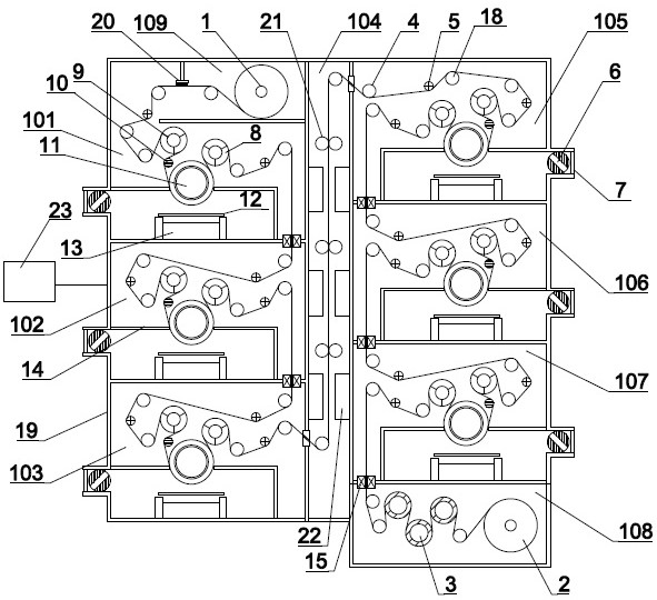
[0047] figure 1 Shown is a schematic structural view of an embodiment of a double-sided multi-station winding vacuum coating machine used in the present invention, the vacuum coating machine mainly includes an unwinding chamber 109, a vacuum evaporation coating chamber, and a magnetron sputtering coating chamber 104. The winding chamber 108 and the winding system. In this embodiment, there are 6 vacuum evaporation coating chambers, which are respectively the vacuum evaporation coating chamber 101, the vacuum evaporation coating chamber 102, the vacuum evaporation coating chamber 103, and the vacuum evaporation coating chamber. Chamber 105, vacuum evaporation coating chamber 106 and vacuum...


PUM


Abstract

The invention discloses a continuous winding vacuum coating method for an ultrathin base film. The method is used for preparing multiple film layers on a flexible base film in the field of new energy power batteries, and mainly comprises the following steps: (1) placing the base film on an unwinding roller in an unwinding chamber of a vacuum coating machine, closing a vacuum chamber, and vacuumizing the vacuum chamber; (2) performing vacuum film penetration on the base film on a winding system by adopting a vacuum film penetration mechanism in a vacuum environment; and (3) when the vacuum degree in vacuum evaporation coating chambers and a magnetron sputtering coating chamber of the vacuum coating machine meets the process requirement, starting the winding system, an evaporation device and a magnetron target. The magnetron sputtering coating chamber is vertically arranged, and the vacuum evaporation coating chambers are arranged on the two sides of the magnetron sputtering coating chamber in a stacked mode. The base film passes through the vacuum evaporation coating chamber on one side, the magnetron sputtering coating chamber and the vacuum evaporation coating chamber on the other side in sequence, evaporation coating and magnetron sputtering coating are conducted respectively, and multiple film layers are plated on the two faces of the base film respectively.

Description

technical field [0001] The invention belongs to the advanced manufacturing technology field of new energy power batteries, in particular to a continuous winding vacuum coating method applied to ultra-thin base film manufacturing of new energy power batteries and a double-sided multi-station winding method used in the method. Vacuum coating machine. Background technique [0002] With the development of optical thin film technology and semiconductor technology, the application of vacuum coating technology in production is becoming more and more extensive and important, and vacuum evaporation coating is the earliest, most common and most widely used vacuum coating process. There are many types and types of vacuum evaporation coating machines. Among them, the intermittent vacuum evaporation coating machine has the longest history. However, due to its shortcomings such as inability to perform continuous coating, small coating area, and low production efficiency, it is difficult t...

Claims


Application Information

Patent Timeline
IPC IPC(8): C23C14/24C23C14/35C23C14/54C23C14/56
CPCC23C14/24C23C14/35C23C14/541C23C14/562Y02E60/10
Inventor 李成林杜雪峰郝明
Owner 辽宁分子流科技有限公司
Learn More